First hardware project
Copyright © Quectel Wireless Solutions Co., Ltd. 2026. All rights reserved.
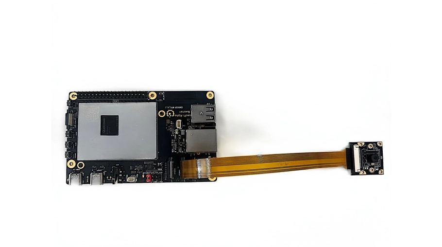
This tutorial walks you through two introductory hardware projects with the Quectel Pi H1 development kit: capturing a photo with an IMX219 camera and monitoring the onboard buttons.
Capture your first photo with an IMX219 camera
If you do not have an IMX219 camera, you can skip this chapter.
Install the camera
Power off the Quectel Pi H1 smart single-board computer.
Locate the MIPI CSI ribbon cable connector labeled CAMERA1 or CAMERA2 on the board.
Insert the IMX219 camera ribbon cable into the connector with its contacts facing down, and secure the latch.
Reconnect the power supply and boot the board.
Note
Do not insert the ribbon cable backward. Its contacts must face the circuit board (downward). Always disconnect the power before installing or removing the ribbon cable.
Capture a photo with the camera
Configure the environment
Before running the photo capture command, set the plugin path (you must set it again each time you open a new terminal window):
export GST_PLUGIN_PATH=/usr/lib/gstreamer-1.0:$GST_PLUGIN_PATH
Capture a photo
Run the following command to capture frames and save them as JPEG files:
max-files controls both the number of photos captured and the number of files saved locally. With max-files=1, the command captures one photo and saves one JPEG file in /home/pi. Setting max-files=n captures n photos and saves n local files.
sudo -E gst-launch-1.0 -e \
    qtiqmmfsrc name=camsrc ! \
    'video/x-raw,format=NV12,width=1280,height=720,framerate=30/1' ! \
    tee name=t ! \
    queue ! videoconvert ! jpegenc ! \
    multifilesink location=/home/pi/shot-%05d.jpg max-files=1
When the pipeline state changes to PLAYING, image capture is active. Press “Ctrl+C” to stop the pipeline.
Note
To capture n photos and save n image files locally, set max-files=n.
Advanced: Capture a photo with Python and OpenCV
Install OpenCV:
sudo apt update
sudo apt install -y python3-opencv
Create the file ~/capture.py:
import cv2

# Access the MIPI camera through a GStreamer pipeline
gst_pipeline = (
    "qtiqmmfsrc name=camsrc ! "
    "video/x-raw,format=NV12,width=1280,height=720,framerate=30/1 ! "
    "videoconvert ! video/x-raw,format=BGR ! appsink"
)

cap = cv2.VideoCapture(gst_pipeline, cv2.CAP_GSTREAMER)

if not cap.isOpened():
    print("Error: Unable to open the camera")
    exit(1)

# Skip the first few frames to allow automatic exposure and white balance to settle
for i in range(30):
    cap.read()

ret, frame = cap.read()
if ret:
    cv2.imwrite("/home/pi/opencv_photo.jpg", frame)
    print("Photo captured successfully and saved to /home/pi/opencv_photo.jpg")
else:
    print("Error: Unable to read an image frame")

cap.release()
Note
The script saves the photo to /home/pi/opencv_photo.jpg. Edit this path to save the file elsewhere.
Run the script (requires sudo privileges):
sudo -E python3 ~/capture.py
Note
The IMX219 is a MIPI CSI camera and does not support the standard V4L2 interface. OpenCV must therefore access it through a GStreamer pipeline. Before running the script, ensure that you have set export GST_PLUGIN_PATH=/usr/lib/gstreamer-1.0:$GST_PLUGIN_PATH.
Explore GPIO
View GPIO pin status
Install the GPIO command-line tools:
sudo apt install -y gpiod
List all GPIO controllers in the system:
sudo gpiodetect
View the status of all pins on a specific controller:
sudo gpioinfo --chip gpiochip4
Each output line represents a GPIO pin. A pin marked with consumer=xxx is in use by a kernel driver.
Note
The onboard KEY1 and KEY2 buttons are managed by the kernel’s gpio-keys and pmic_resin drivers and are exposed to user space as standard Linux input devices. Therefore, use evtest or evdev to read button events instead of manipulating GPIO pins directly.
Verify the buttons with evtest
Quectel Pi H1 smart single-board computer provides two user buttons, KEY1 and KEY2, which are exposed through the Linux input subsystem. Event device numbers can change between system versions. Run sudo evtest first to identify the event devices for gpio-keys and pmic_resin; the table below shows the mapping used in this example.
Button |
Input device |
Mapped key code |
|---|---|---|
KEY1 |
/dev/input/event3 |
KEY_VOLUMEDOWN (114) |
KEY2 |
/dev/input/event1 |
KEY_VOLUMEUP (115) |
Install the evtest utility:
sudo apt install -y evtest
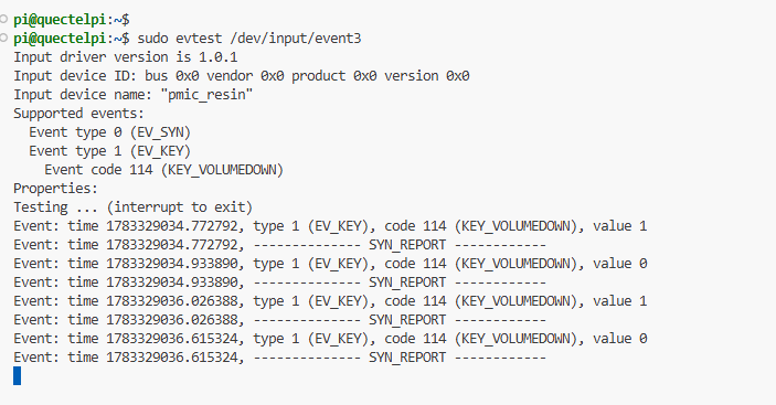
Run the following command to monitor KEY1:
sudo evtest /dev/input/event3
Press KEY1. The terminal displays the button events in real time:
Event: time ..., type 1 (EV_KEY), code 114 (KEY_VOLUMEDOWN), value 1   ← Pressed
Event: time ..., type 1 (EV_KEY), code 114 (KEY_VOLUMEDOWN), value 0   ← Released
Press “Ctrl+C” to exit. Similarly, you can use sudo evtest /dev/input/event1 to monitor KEY2.
Monitor button events with Python
Install the evdev library:
pip install evdev
Create the file ~/button_monitor.py:
from evdev import InputDevice, ecodes
import selectors

dev_key1 = InputDevice("/dev/input/event3")
dev_key2 = InputDevice("/dev/input/event1")

print(f"Monitoring KEY1: {dev_key1.name}")
print(f"Monitoring KEY2: {dev_key2.name}")
print("Press Ctrl+C to exit")

sel = selectors.DefaultSelector()
sel.register(dev_key1, selectors.EVENT_READ)
sel.register(dev_key2, selectors.EVENT_READ)

try:
    while True:
        for key, _ in sel.select():
            device = key.fileobj
            for event in device.read():
                if event.type == ecodes.EV_KEY and event.value == 1:
                    if event.code == ecodes.KEY_VOLUMEDOWN:
                        print("KEY1 pressed!")
                    elif event.code == ecodes.KEY_VOLUMEUP:
                        print("KEY2 pressed!")
except KeyboardInterrupt:
    print("\nMonitoring stopped")
Run the script:
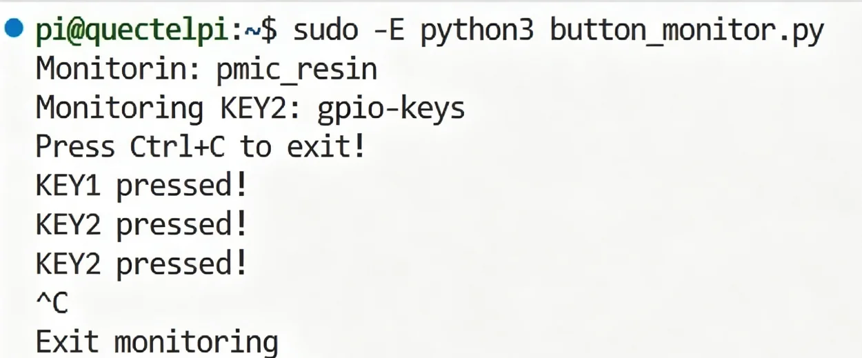
sudo -E python3 ~/button_monitor.py
Press KEY1 or KEY2. The terminal displays the corresponding message. Press “Ctrl+C” to exit.
Note
Accessing Linux input devices requires root privileges, so run the script with sudo.
Troubleshooting
Q: The photo capture command reports “no element qtiqmmfsrc”
Set the plugin path first:
export GST_PLUGIN_PATH=/usr/lib/gstreamer-1.0:$GST_PLUGIN_PATH
Then run the photo capture command.
Q: The photo capture command reports “Failed to connect to bus”
Ensure that the command includes the sudo -E prefix because the camera plugin requires root privileges.
Q:*evtest*does not display button events
The device numbers may differ from those in the examples. Run sudo evtest without arguments to list all input devices. Then locate the gpio-keys and pmic_resin devices and use their corresponding event numbers.
Q: The Python script reports a permission error
Both input devices and the camera require root privileges:
Button script: sudo -E python3 ~/button_monitor.py
Photo capture script: sudo -E python3 ~/capture.py