User Guide
Copyright © Quectel Wireless Solutions Co., Ltd. 2026. All rights reserved.
This user guide aims to provide users with comprehensive usage instructions for the Quectel Pi M1 / L1 smart main control board, covering device specification introduction, power supply, display, and functional descriptions, operation methods, and precautions for various peripherals (camera, Wi-Fi/BT, cellular network, Ethernet, audio, USB, etc.). It helps users quickly understand the device performance, master the usage process, solve application problems, and provide clear and detailed reference for the debugging, deployment, operation and maintenance of the device.
Specification Introduction
Please go to the Specification Introduction page for details.
Display
MIPI
This document details the usage of the MIPI—DSI display for the Quectel Pi M1 / L1 smart main control board, and takes the Waveshare 8-inch DSI interface IPS capacitive touch screen as an example for detailed explanation.
MIPI Screen Connection
Hardware Interface Connection
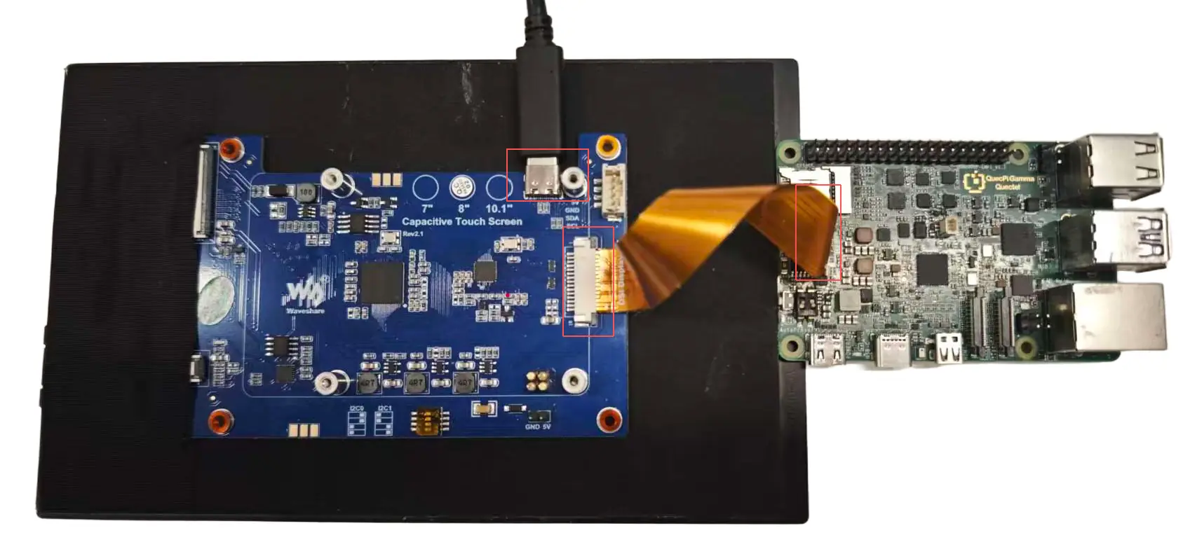
This screen has 4 power supply interfaces, you can choose any one of them. The example selects the “1” interface for power supply.
Type-C interface.
I2C communication and power supply interface.
5V input and output interface.
I2C communication and power supply interface. Align the screw holes with the Quectel Pi M1 / L1 smart main control board and tighten them to ensure a firm connection between the pogo pins and the 40-pin header.
Power On and Boot Up
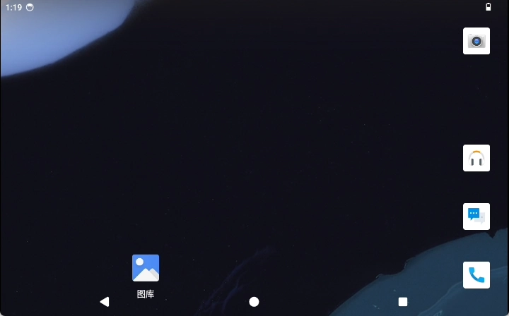
After powering on and booting up, you will enter the system desktop.
Function Usage
How to Use the Touch Function
After connecting the MIPI display and powering on the device, you can use the touch function directly.
Adjust Audio and Display
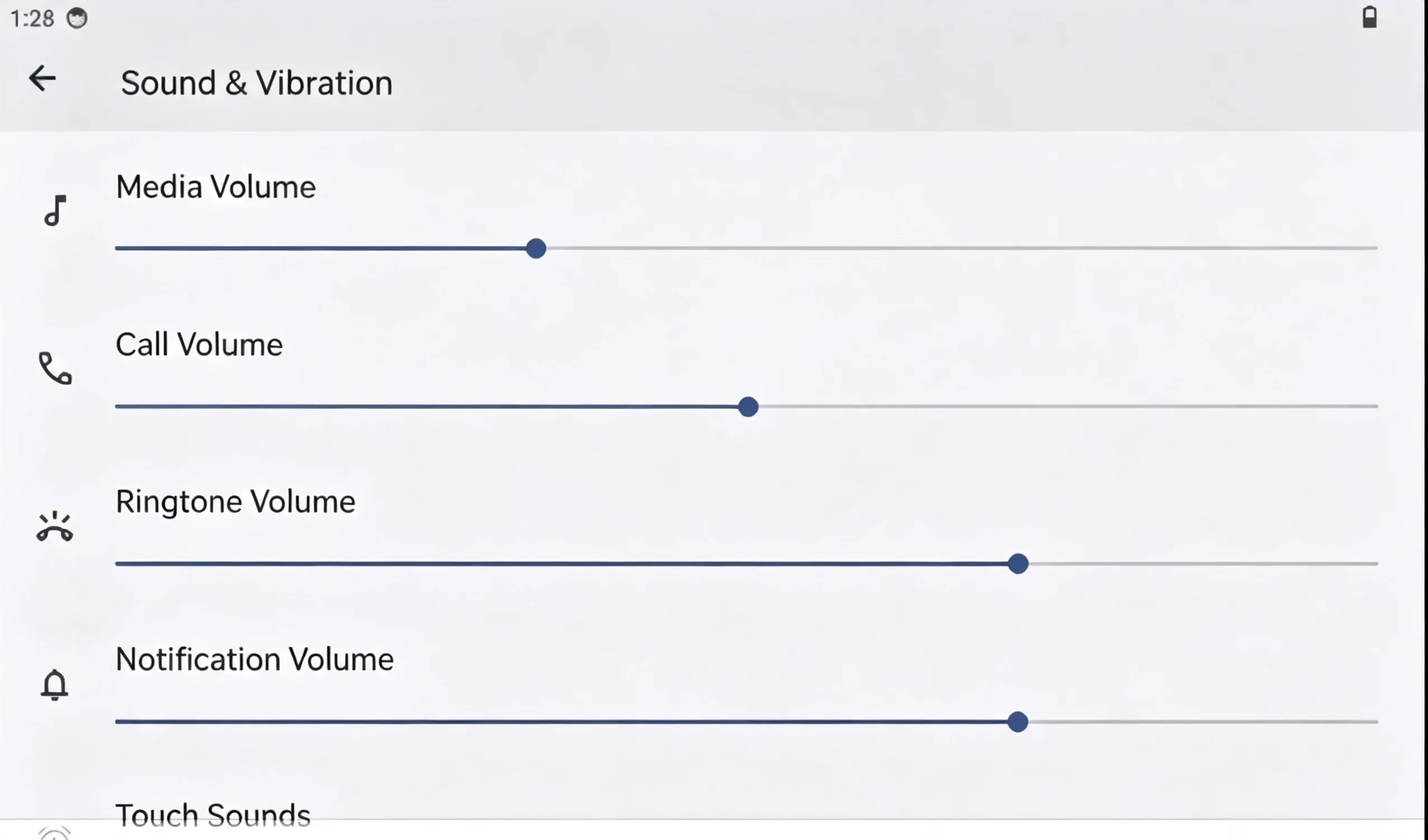
For specific audio configuration, please go to: Android Desktop → Menu → Settings → Sound & Vibration to adjust audio settings.
For specific display configuration, please go to: Android Desktop → Menu → Settings → Display to adjust display settings.
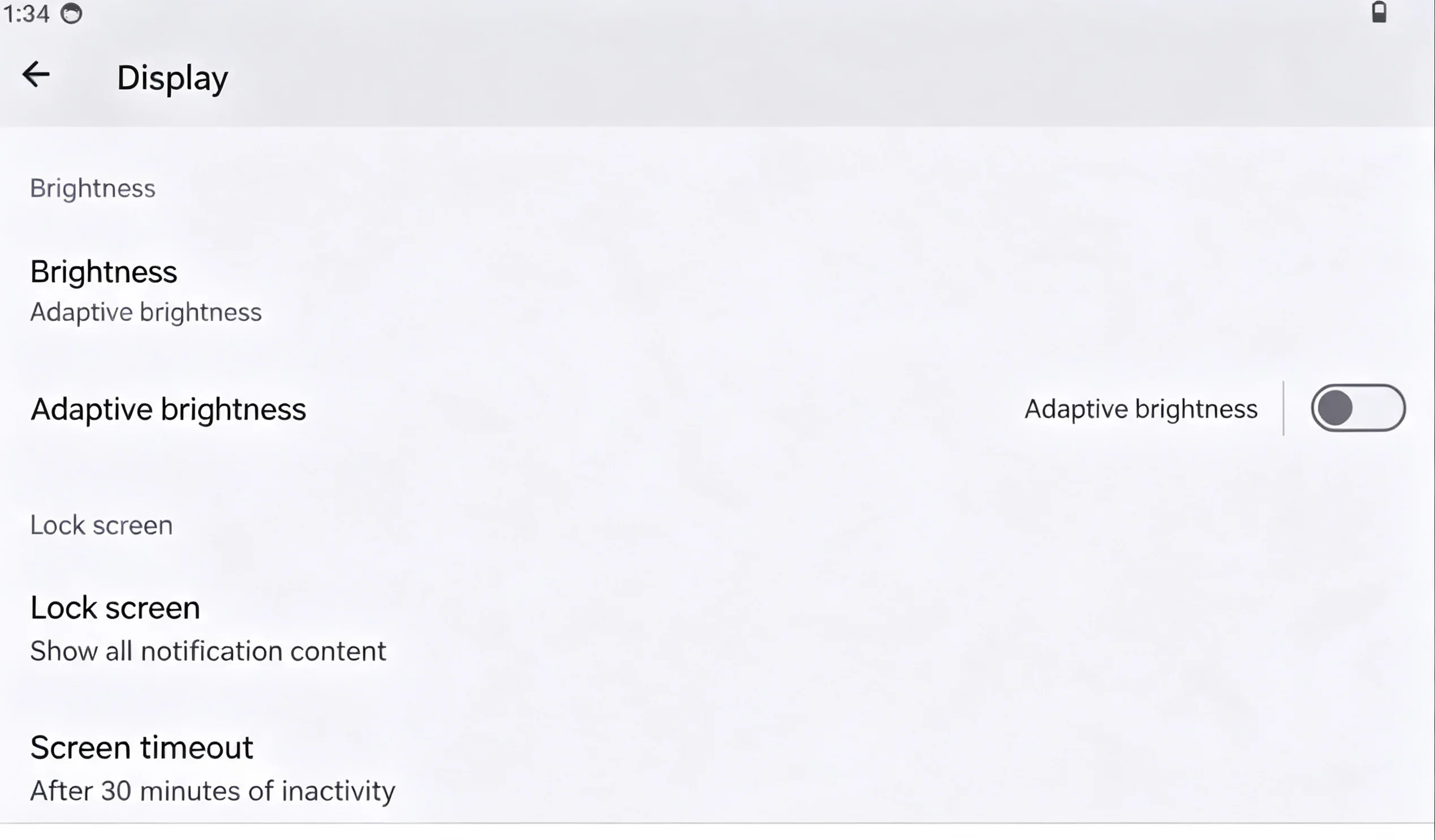
Note: Only the operation diagrams for screen and sound are shown here. The operation steps for other settings such as battery, storage, wallpaper, location information, etc. are consistent with those for screen and sound.
Video Playback Function
Video Playback Function on Android Desktop
Use the adb tool to push the video file to the smart main control board.
adb push "E:\FeiShu\Animal World.mp4" /sdcard/DCIM     # Push the relevant video to the DCIM directory of the SD card on the smart main control board
# Enter the smart main control board
su    # Switch to the root user
am broadcast -a android.intent.action.MEDIA_SCANNER_SCAN_FILE -d file:///sdcard/DCIM/Animal World.mp4    # Rescan this file in the media library
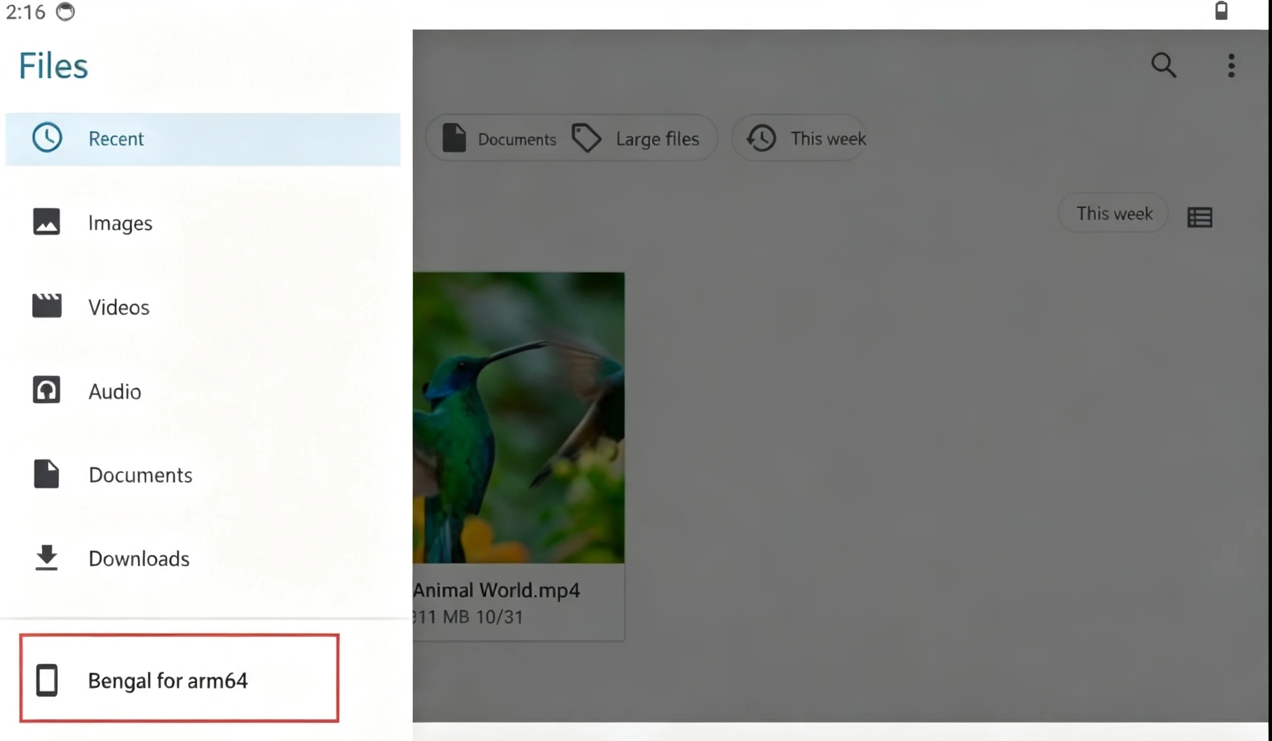
For specific operations, please go to:
Android Desktop → File Manager → Video File → Play Video.

Audio Playback Function
Audio Playback Function on Android Desktop:
Note: To play audio, you need to connect a speaker to the Quectel Pi M1 / L1 smart main control board.
Use the adb tool to push the audio file to the smart main control board.
adb push E:\eage\test.mp3 /sdcard/Music # Push the audio to the Music directory of the SD card on the smart main control board
# Enter the smart main control board
su    # Switch to the root user
am broadcast -a android.intent.action.MEDIA_SCANNER_SCAN_FILE -d file:///sdcard/Music/test.mp3     # Rescan this file in the media library
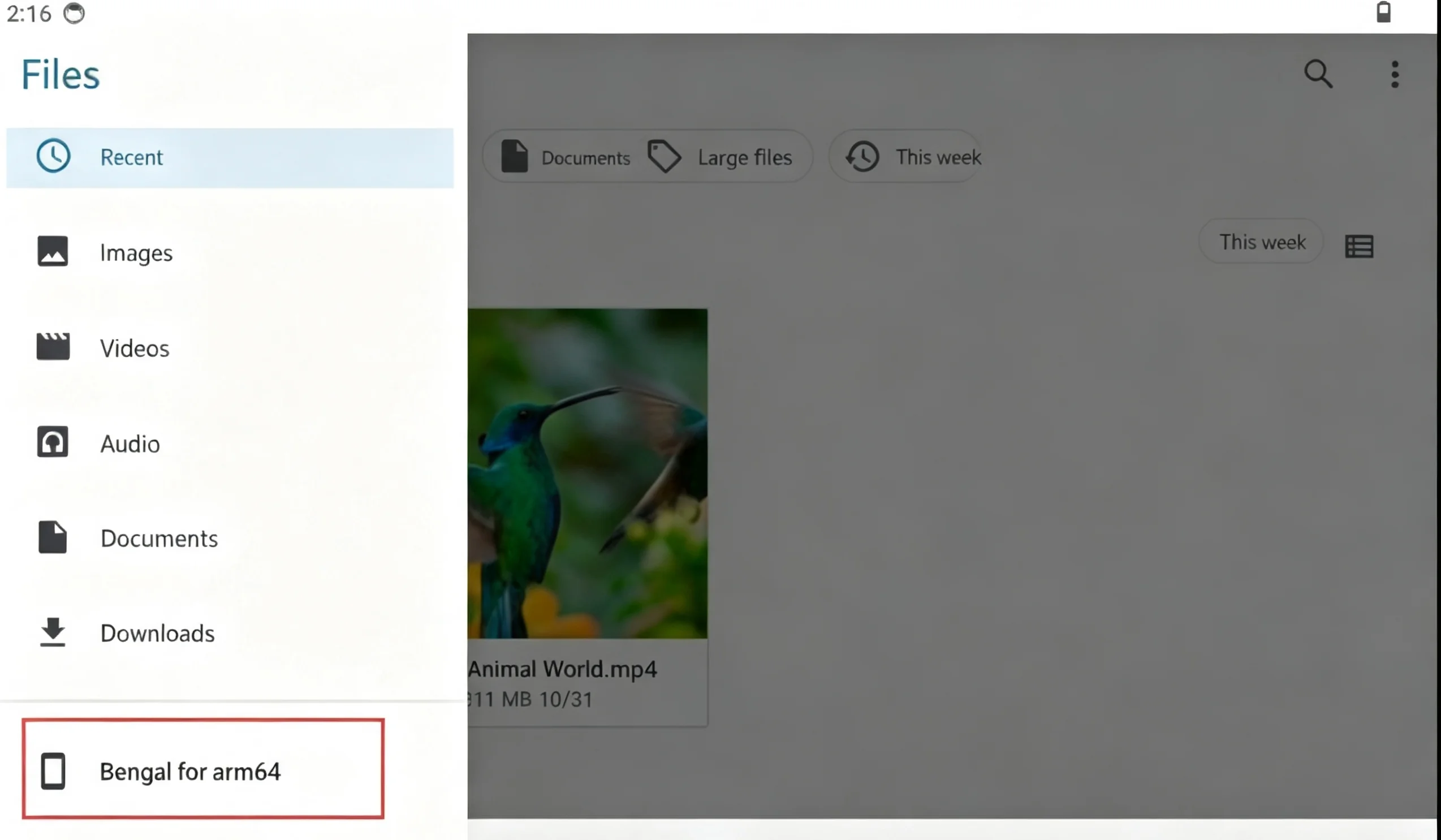
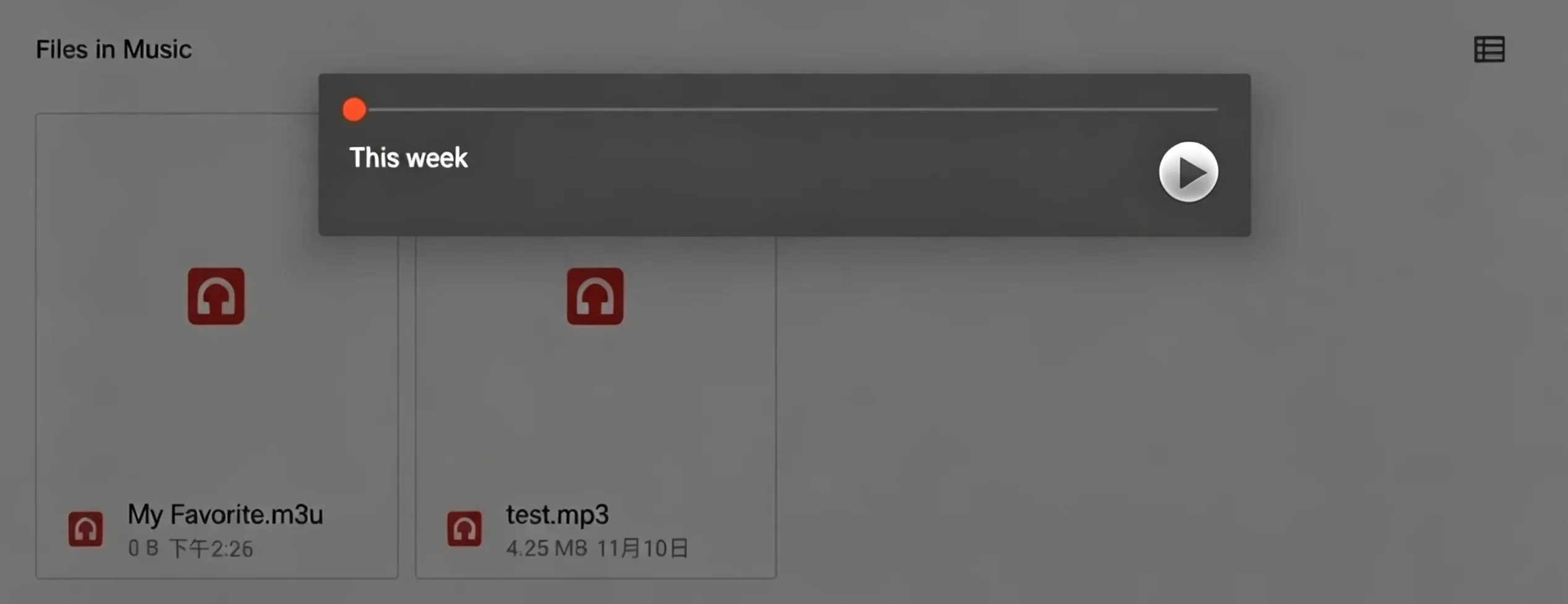
For specific operations, please go to:
Android Desktop → File Manager → Play Audio.
HDMI
This section details the usage of the Micro HDMI display for the Quectel Pi M1 / L1 smart main control board, and takes the 10.1-inch HDMI display as an example for detailed explanation.
Micro HDMI Screen Connection
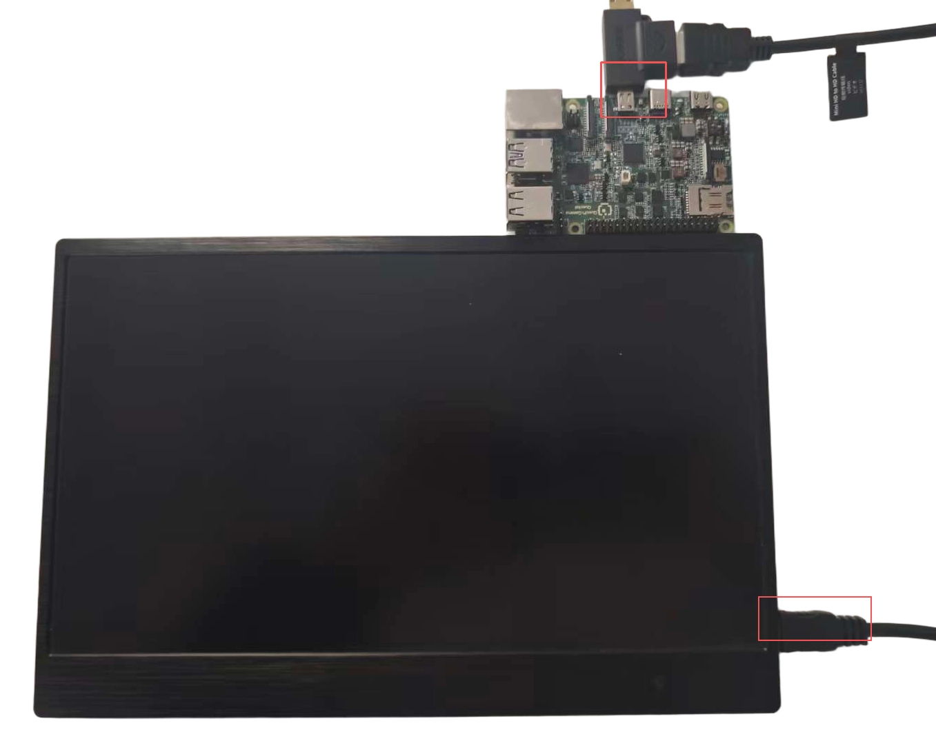
Hardware Interface Connection
Power On and Boot Up
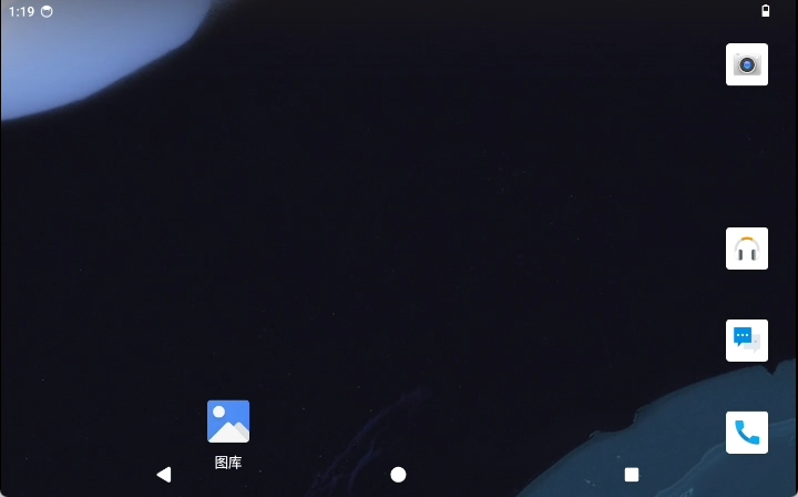
After powering on and booting up, you will enter the system desktop.
Function Usage
How to Use the Touch Function
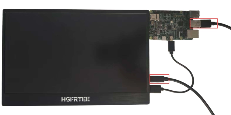
After the HDMI display is powered on and booted up, you need to connect the USB port to the HDMI screen.
Note: This function requires an HDMI screen with touch function.
Connect according to the following figure:
Adjust Audio and Display
Note: After connecting to an HDMI monitor, the resolution is adaptive and cannot be changed. Currently supported HDMI resolutions are 3840 × 2160, 1920 × 1080, 1280 × 720, 720 × 480
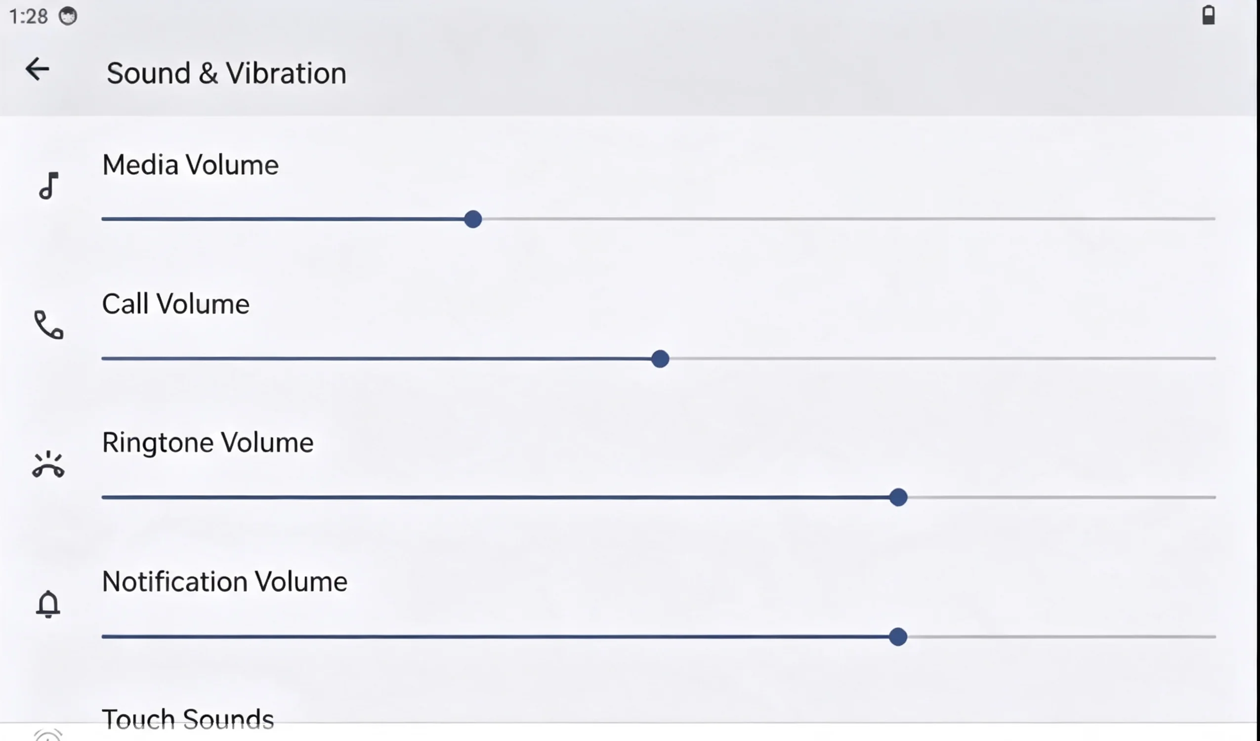
For specific audio configuration, please go to: Android Desktop → Menu → Settings → Sound & Vibration to adjust audio settings.
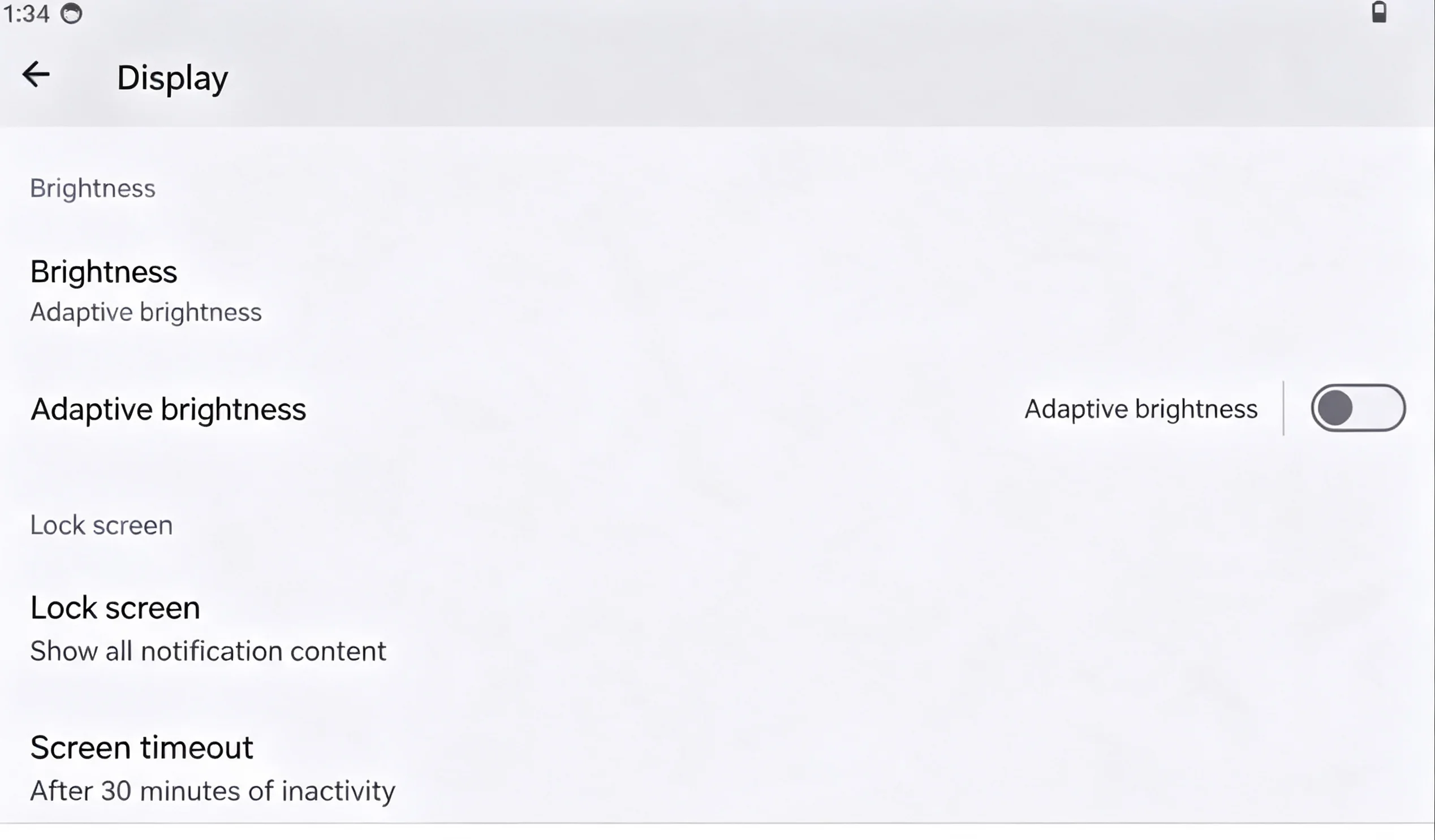
For specific display configuration, please go to: Android Desktop → Menu → Settings → Display to adjust display settings.
Video Playback Function
Video Playback Function on Android Desktop
Use the adb tool to push the video file to the smart main control board.
adb push "E:\FeiShu\Animal World.mp4" /sdcard/DCIM     # Push the relevant video to the DCIM directory of the SD card on the smart main control board
# Enter the smart main control board
su    # Switch to the root user
am broadcast -a android.intent.action.MEDIA_SCANNER_SCAN_FILE -d file:///sdcard/DCIM/Animal World.mp4    # Rescan this file in the media library
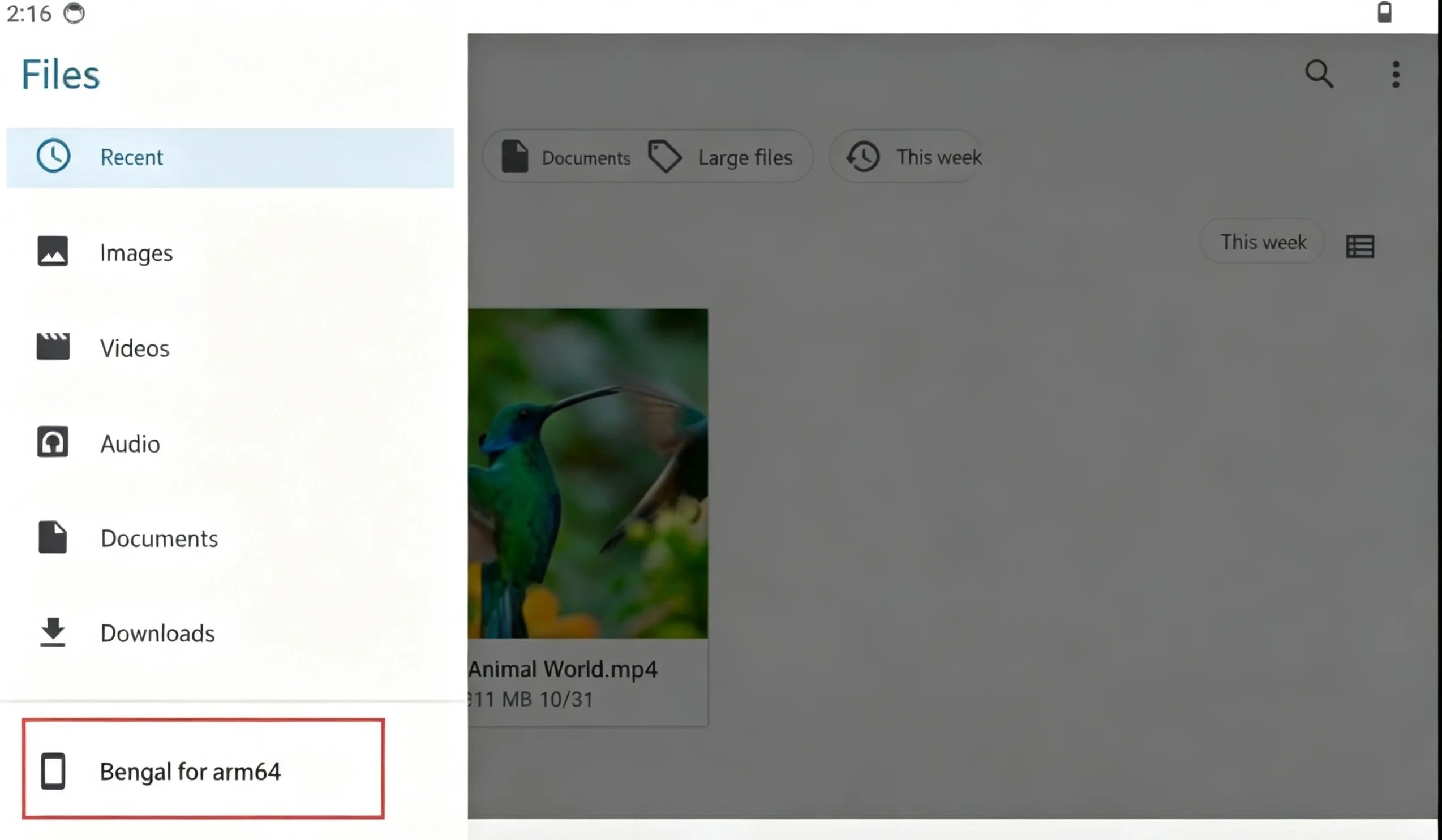
For specific operations, please go to:
Android Desktop → File Manager → Video File → Play Video.

Audio Playback Function
Audio playback function on Android Desktop:
Note: To play audio, the speaker needs to be connected to the Quectel Pi M1 / L1 intelligent main control board.
Use the adb tool to push the audio file to the intelligent main control board.
```SHELL
adb push E:\eage\test.mp3 /sdcard/Music #Push the audio to the Music directory of the SD card on the intelligent main control board

#Access the intelligent main control board
su    #Switch to root user
am broadcast -a android.intent.action.MEDIA_SCANNER_SCAN_FILE -d file:///sdcard/Music/test.mp3     #Rescan this file in the media library
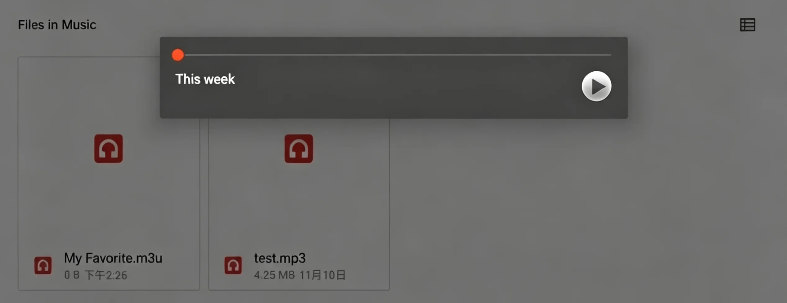
1. For specific configurations, follow the path: `Android Desktop -> File Manager -> Play Audio`.

```{image} images/image_VMpJbv4X0omvUCxCQxVcOCS9nYb.webp
:width: 2548px
:height: 1485px
:align: center
Advanced Functions
Hot Plugging of HDMI Screen
HDMI screens support hot plugging function. You can plug and unplug the HDMI screen while the system is running, and the system will automatically recognize it and display the picture.
How to Use Hot Plugging
When the system is running, directly insert the HDMI screen into the Micro HDMI interface of the intelligent main control board.
The system will automatically detect the HDMI device and start the display output.
If you need to disconnect the HDMI screen, you can directly pull out the Micro HDMI cable, and the system will automatically switch the display output.
Notes on Hot Plugging
The hot plugging function only supports displays connected through the Micro HDMI interface.
Screens connected using a DP to Micro HDMI adapter may not support hot plugging normally.
Please avoid frequent operations during plugging and unplugging. It is recommended that the interval between each plugging and unplugging be no less than 5 seconds.
Camera
This document takes the IMX219 camera module as an example, introduces in detail the identification and connection methods of the MIPI CSI camera interface of the Quectel Pi M1 / L1 intelligent main control board, and provides guidance on function usage and solutions to common problems.
Hardware Interface
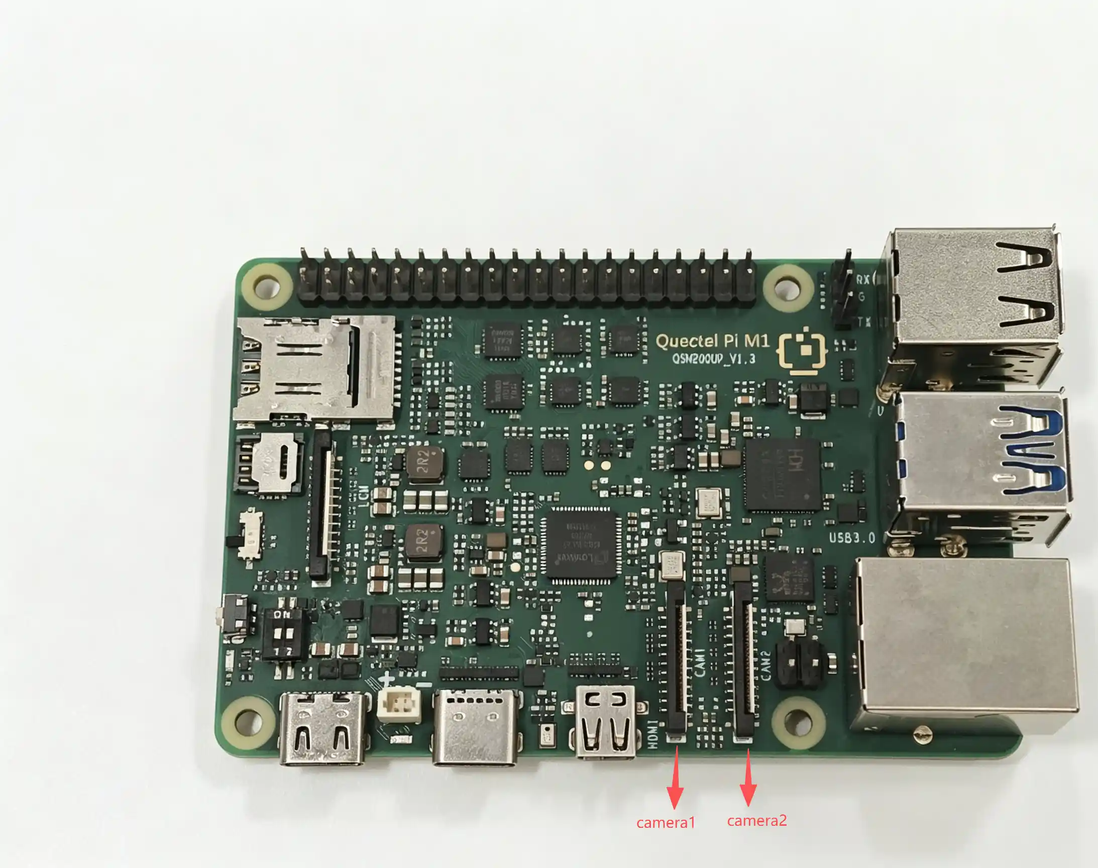
The Quectel Pi M1 / L1 intelligent main control board supports a total of two MIPI CSI interfaces for cameras, as shown in the following figure:
Quick Start
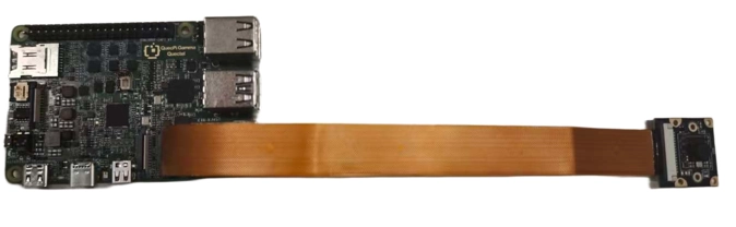
Connect the camera as shown in the figure below. When connecting, pull up the black latch part of the connector, insert the FPC cable into the first CSI card slot, note that the gold fingers of the cable face the metal contact surface inside the board, press down the latch, and confirm that the FPC cable is stable and not loose.
Refer to the display section to connect the display screen.
Function Usage
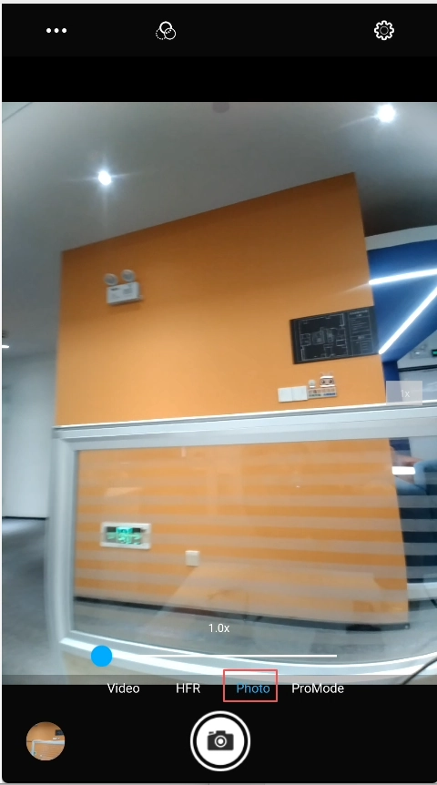
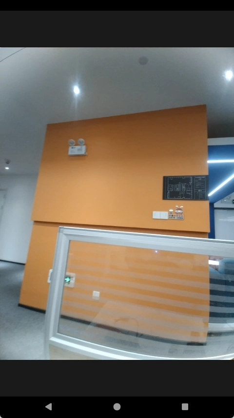
Preview
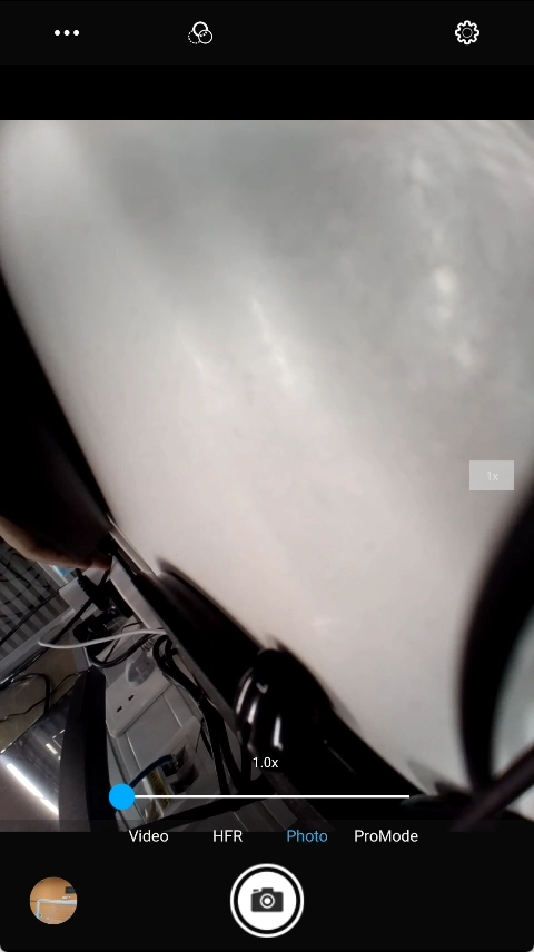
The configurations and parameters required for the IMX219 camera have been pre-integrated in the kernel. The specific operation steps are as follows: Connect the camera to **Quectel-Pi-M1 / L1 , Power on and boot -> Android Desktop -> Camera -> Camera Interface`.
Video Recording
Specific operation steps: Camera Interface -> Click Record -> Start recording video -> Save to album. The recorded video files can also be found through the file system.
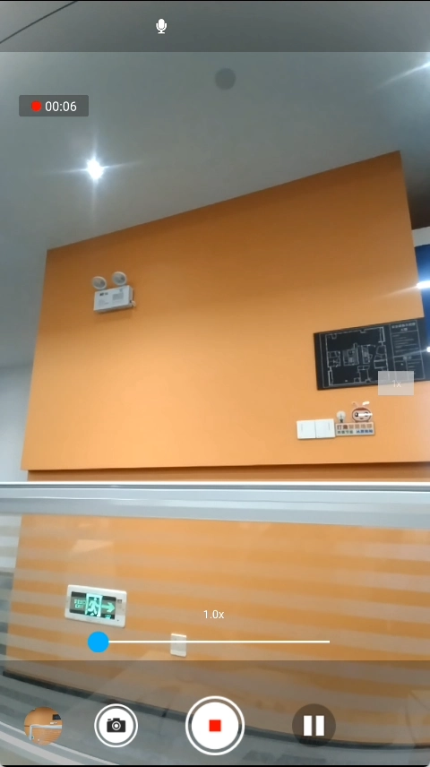
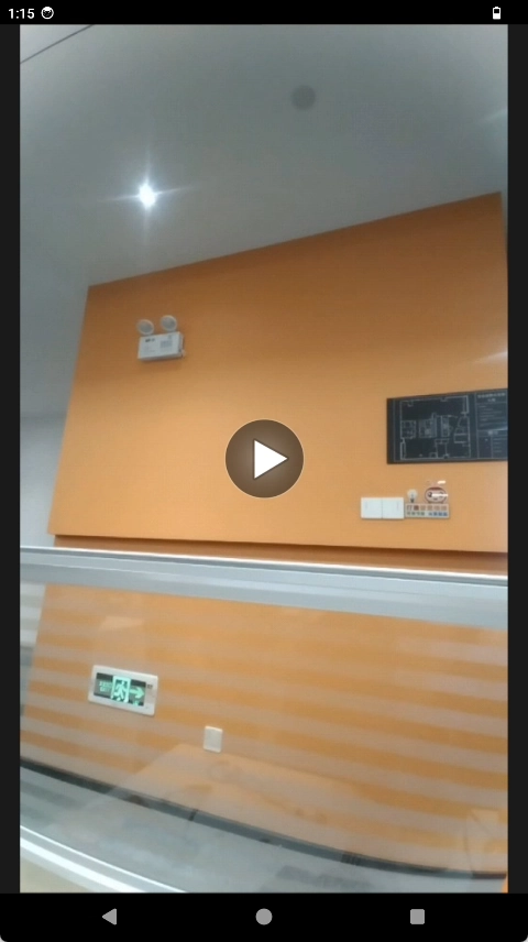
Photo Taking
Specific operation steps: Camera Interface -> Click Photo -> Start taking photos -> Save to album. The photo files can also be found through the file system.
Wi-Fi/BT
The Quectel Pi M1 / L1 intelligent main control board supports Wi-Fi and Bluetooth (BT) connections. Users need to connect a MIPI display, boot into the Android desktop, and then select the target network or device to connect to, so as to realize wireless communication.
Wi-Fi Function Usage
Enable and Connect Wi-Fi
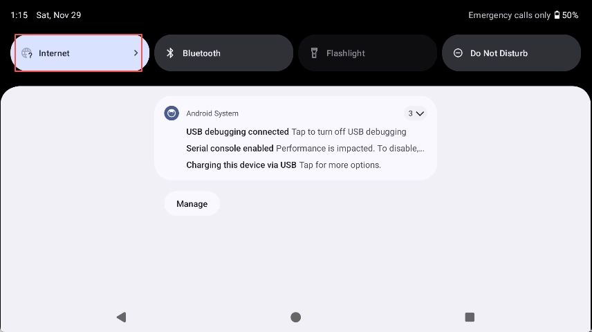
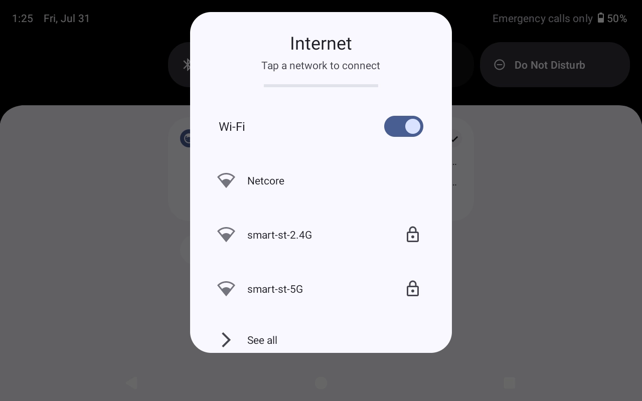
The specific operation steps are as follows: Connect MIPI display -> Power on and boot -> Android Desktop -> Pull down the desktop -> Click the Wi-Fi icon -> Enter the Wi-Fi interface.
Bluetooth Function Usage
The Quectel Pi M1 / L1 intelligent main control board has a built-in Bluetooth function and supports connecting Bluetooth peripherals.
Enable Bluetooth
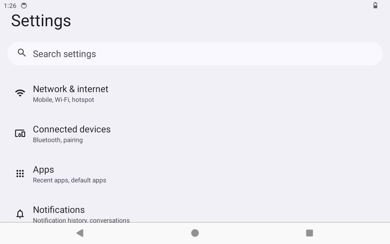
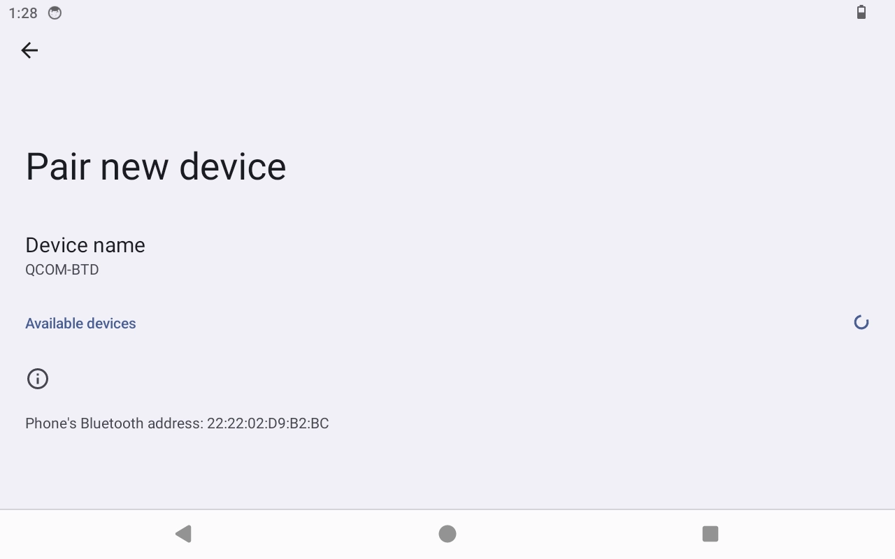
The specific operation steps are as follows: Connect MIPI display -> Power on and boot -> Android Desktop -> Pull down the desktop -> Click the BT icon -> Enter the Bluetooth (BT) interface.
Cellular Network
Cellular Network is a wide area network architecture based on radio communication, widely used in mobile communication and Internet of Things devices. Its core feature is dividing the coverage area into multiple “cells”, each of which is provided with wireless access by a base station. Terminal devices connect to the operator’s core network through the base station to realize voice, SMS and data services.
This section mainly introduces the method of using USIM to connect to the network.
Supports dual SIM dual standby. This document only introduces USIM.
Only supports 4G LTE network.
Hardware Connection
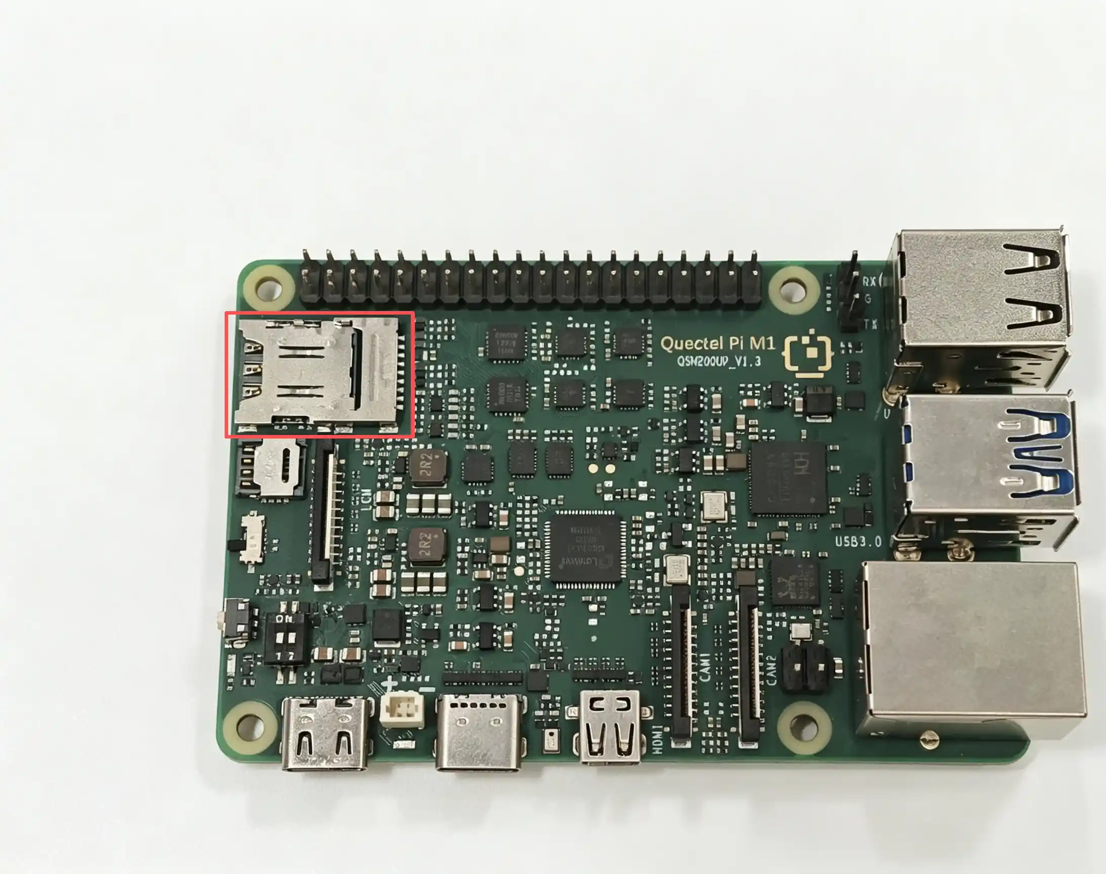
SIM card slot
Nano SIM pluggable card holder.
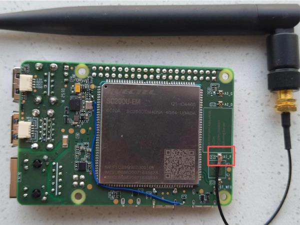
SIM card antenna interface
IPEX-4TH antenna holder.
Quick Start
Boot Up
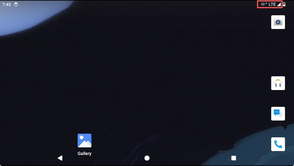
After entering the system, you can check whether the SIM card is normally recognized. The normal recognition is shown in the following figure.
Network Connection Confirmation
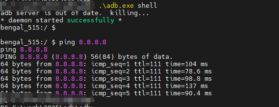
Use adb to enter the system and ping 8.8.8.8 to confirm whether the network connection is normal.
Function Usage
Turn on Cellular Network
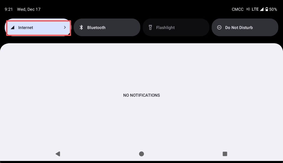
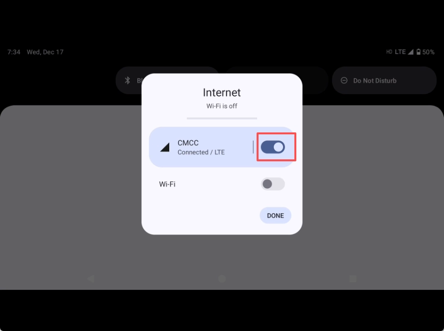
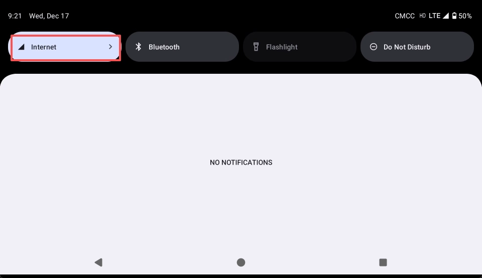
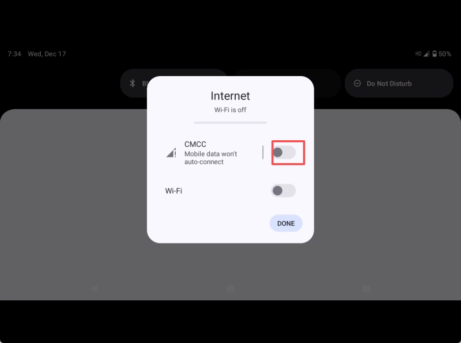
Swipe down from the top of the screen, the drop-down menu will display the Internet option. Click to select the corresponding LTE toggle switch, and it will light up to indicate the on state.
Turn off Cellular Network
Swipe down from the top of the screen, the drop-down menu will display the Internet option. Click to select the corresponding LTE toggle switch, and it will dim to indicate the off state.
Frequently Asked Questions
What may be the reason why the wireless network card is activated successfully but network communication cannot be performed?
Generally, the following two situations may cause this problem:
SIM card arrears For some SIM cards in arrears, the module can still successfully register to the network and activate the cellular wireless network card, but the operator will restrict the module from performing actual network communication.
APN configuration problem The SIM card supports accessing a special network through a specific APN, and the user has also configured the APN for accessing the special network. At this time, the device accesses the special network instead of the Internet. If the user attempts to access the Internet in this situation, the access will fail. For specific APN configuration, please go to Settings -> Network & Internet -> Internet -> CMCC (connected/LTE) -> Access Point network in sequence, and then configure a new APN for network connection.
Ethernet
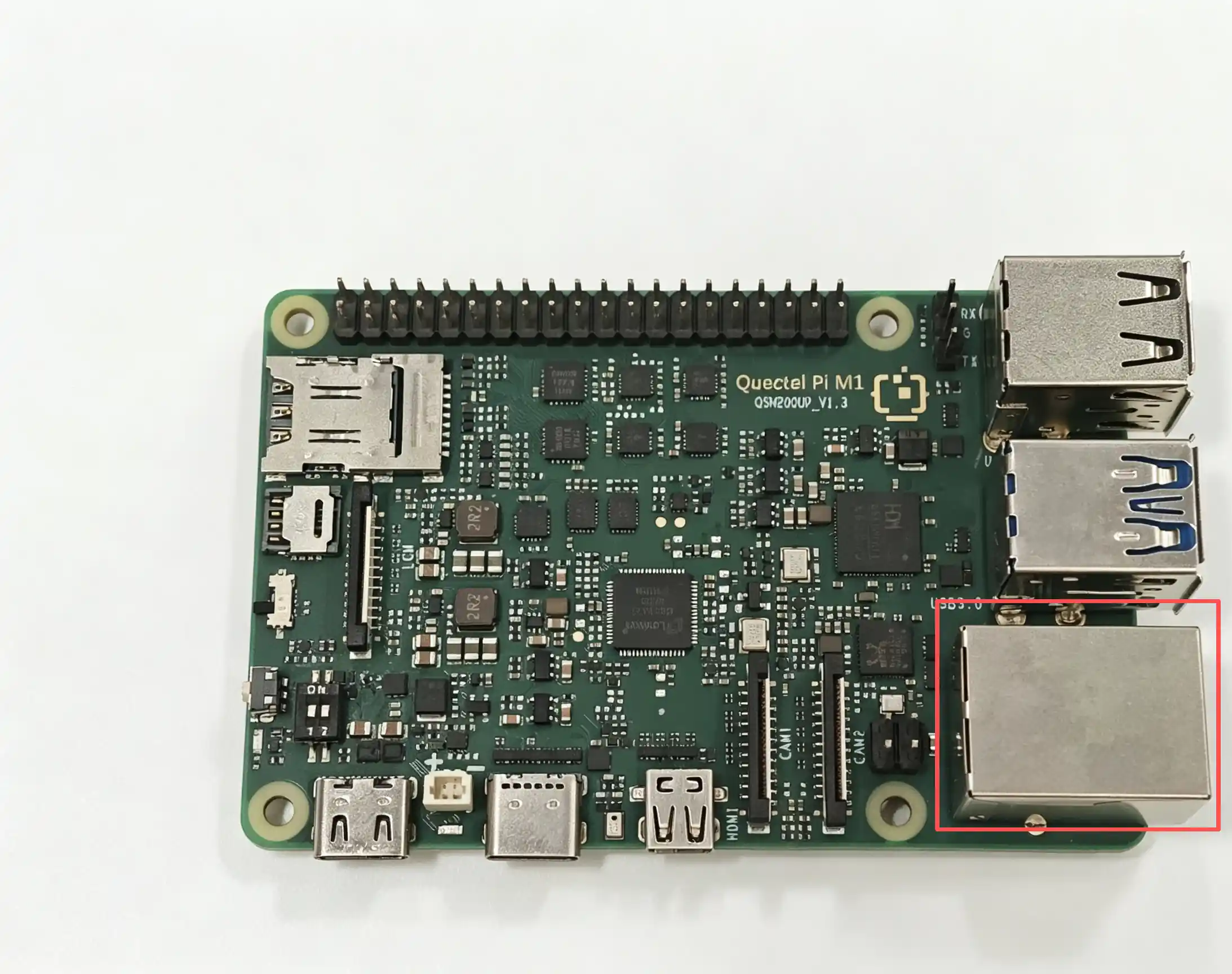
The Quectel Pi M1 / L1 smart main control board is equipped with 1 standard RJ45 interface, supporting Ethernet with a communication rate of 10/100/1000 Mbps.
Requirements for Ethernet cables: Only supports straight-through cables, does not support crossover cables.
Hardware Interface
View Network Configuration
The system enables DHCP to automatically obtain network configuration by default.
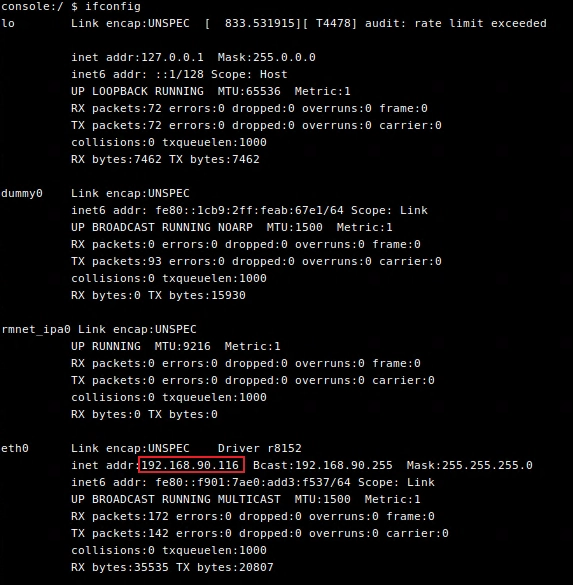
Enter the ifconfig command in the terminal to view the network interface address:
ifconfig
Output example: The 192.168.90.116 after inet addr: is the local IP address.
Enter the ip route command in the terminal to view the network routing information:
ip route
Output example:

View DNS server address:
dumpsys connectivity | grep -o ' DnsAddresses: \[[^]]*\]'
Output example:

Test Network
**Execute theping**command to test the network connection
Execute the
ping 8.8.8.8command. If the ping is successful (response is received), it indicates that the external network connection is normal.Execute the
ping www.example.comcommand. If the ping is successful, it indicates that the external network connection is normal and the DNS resolution function is normal.
Audio Function
This document provides a concise guide to the operation of the audio system. The system adopts the dual-layer audio architecture of ALSA + PulseAudio, providing a complete audio solution from the underlying driver to the application layer.
At the hardware level, the system supports:
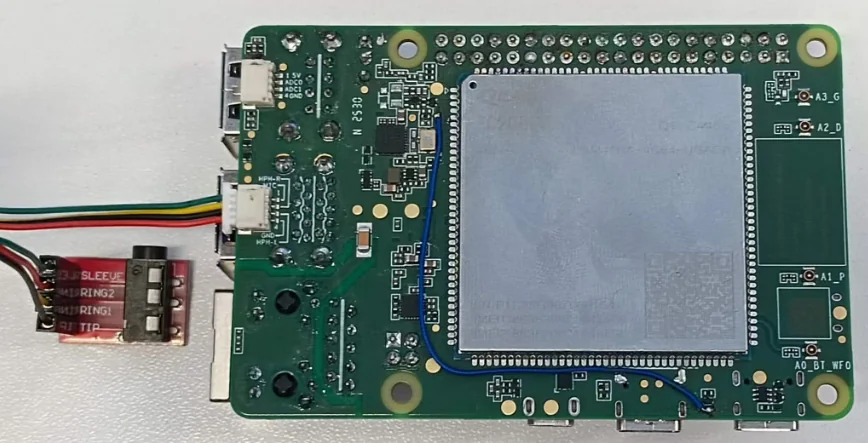
External microphone input (external SH1.0-4P audio to headphone interface)
External speaker/headphone output, which can realize full-duplex communication of headphone playback and microphone input
At the software level, the system provides a set of standard audio configuration and debugging commands for completing common operations such as device inspection, recording, playback and volume control.
With this document, you can quickly locate and solve most audio-related problems without in-depth complex configuration.
Hardware Interface
External SH1.0-4P audio to headphone interface
On-board MEMS microphone

View Sound Card Information
You can check the loading status of the system sound card and PCM devices through the following commands:
View the sound card list:
cat /proc/asound/cards

View the list of assigned pcm streams:
cat /proc/asound/pcm
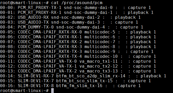
Note: If the system fails to detect sound card information or PCM streams, both ALSA and PulseAudio cannot work properly.
Function Usage
Audio Recording
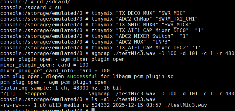
Recording under Android system
tinymix "TX DEC0 MUX" "SWR_MIC"
tinymix "ADC2 ChMap" "SWRM_TX2_CH1"
tinymix "TX SMIC MUX0" "SWR_MIC4"
tinymix "TX_AIF1_CAP Mixer DEC0"  "1"
tinymix "ADC2_MIXER Switch"  "1"
tinymix "ADC2 MUX"  "INP3"
tinymix 'TX_AIF1_CAP Mixer DEC2' '1'
agmcap ./testMic3.wav -D 100 -d 101 -c 1 -r 48000 -i "CODEC_DMA-LPAIF_RXTX-TX-3"
End recording
Press “Ctrl” + “Z” to end the recording:
Headset Microphone Recording
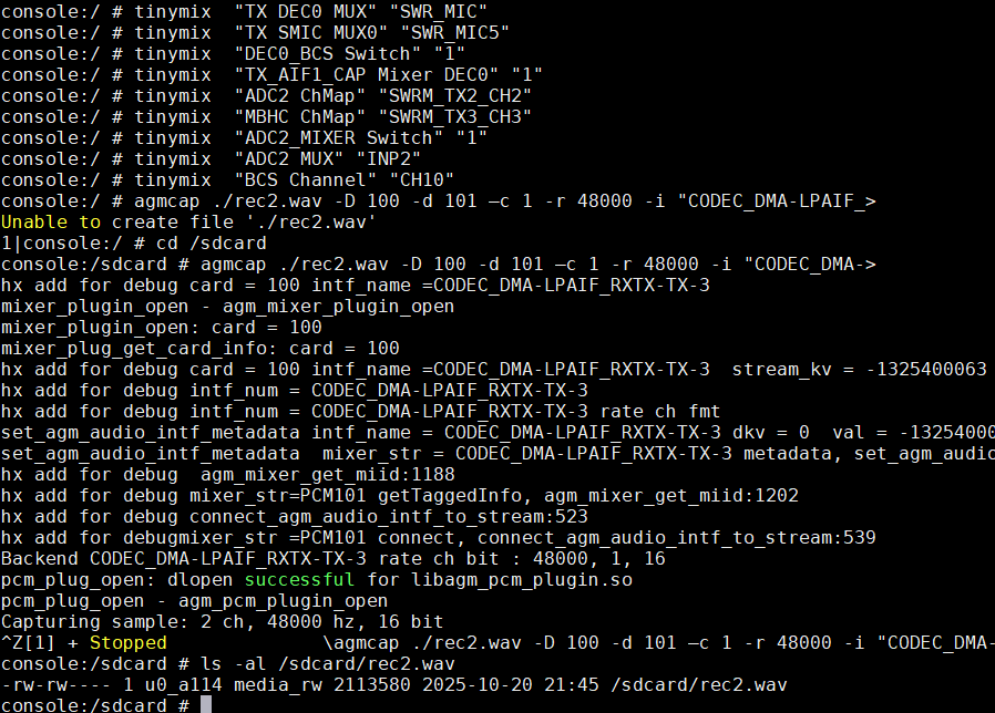
Recording under Android system
tinymix  "TX DEC0 MUX" "SWR_MIC"
tinymix  "TX SMIC MUX0" "SWR_MIC5"
tinymix  "DEC0_BCS Switch" "1"
tinymix  "TX_AIF1_CAP Mixer DEC0" "1"
tinymix  "ADC2 ChMap" "SWRM_TX2_CH2"
tinymix  "MBHC ChMap" "SWRM_TX3_CH3"
tinymix  "ADC2_MIXER Switch" "1"
tinymix  "ADC2 MUX" "INP2"
tinymix  "BCS Channel" "CH10"
agmcap ./rec2.wav -D 100 -d 101 –c 1 -r 48000 -i "CODEC_DMA-LPAIF_RXTX-TX-3"
Note: During operation, make sure that the current directory has write permission.
Audio Playback
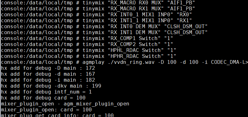
The onboard speaker is not soldered, so use the external headset channel for playback.
Headset Playback
Playback under Android system (3.5 mm headset)
adb root
adb shell
cd /data/local/tmp
tinymix "RX_MACRO RX0 MUX" "AIF1_PB"
tinymix "RX_MACRO RX1 MUX" "AIF1_PB"
tinymix "RX INT0_1 MIX1 INP0" "RX0"
tinymix "RX INT1_1 MIX1 INP0" "RX1"
tinymix "RX INT0 DEM MUX" "CLSH_DSM_OUT"
tinymix "RX INT1 DEM MUX" "CLSH_DSM_OUT"
tinymix "RX_COMP1 Switch" "1"
tinymix "RX_COMP2 Switch" "1"
tinymix "HPHL_RDAC Switch" "1"
tinymix "HPHR_RDAC Switch" "1"
agmplay ./vvdn_ring.wav -D 100 -d 100 -i CODEC_DMA-LPAIF_RXTX-RX-0 -dkv 0xA2000002
Troubleshooting
Problem |
Possible Causes |
|---|---|
No recording file generated |
|
Audio playback failed |
|
USB
USB host refers to the system or hardware that can control and manage USB devices. It is responsible for providing power, data transmission and management functions for connected USB devices (such as USB flash drives, keyboards, mice, etc.).
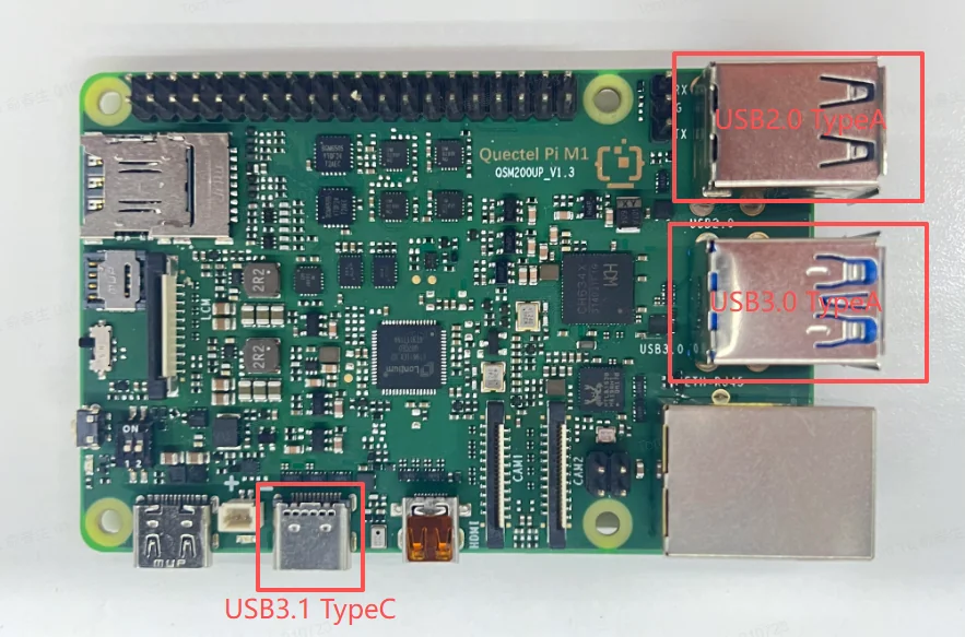
The Quectel Pi M1/L1 intelligent main control board comes with 2 standard USB 3.0 Type-A interfaces, 2 standard USB 2.0 Type-A interfaces and 1 USB 3.1 Type-C interface. The maximum data transfer rate of the USB 2.0 interface can reach 480 Mbps, and that of the USB 3.1 interface can reach 5 Gbps.
Function Usage
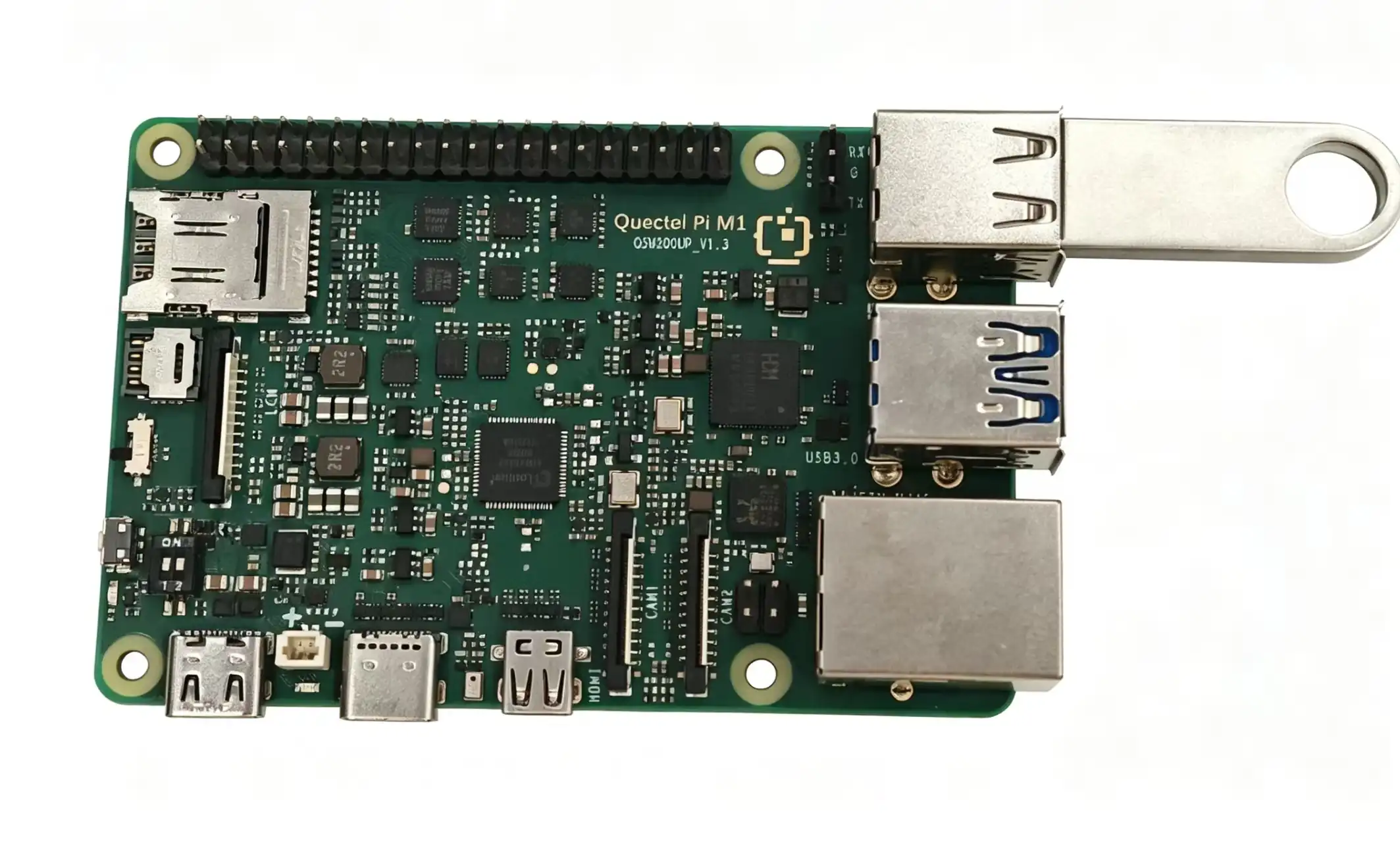
Connect a USB Flash Drive
Insert a USB flash drive into the Type-A port.
The USB device is displayed in the notification bar.
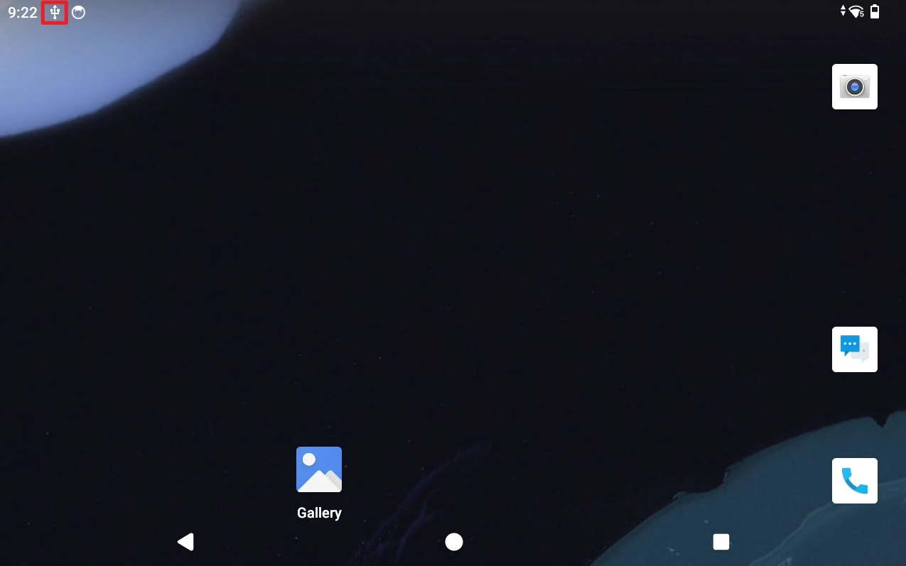
Pull down to expand the notification bar.
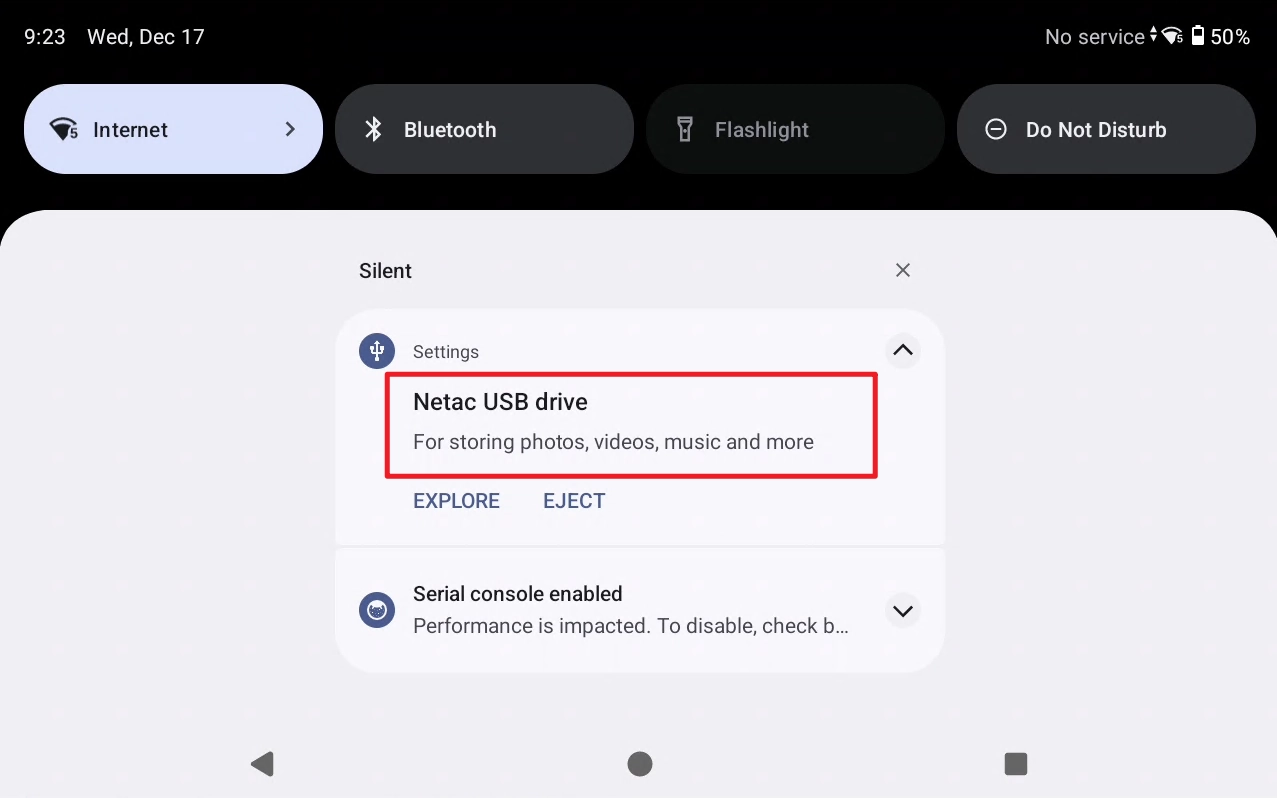
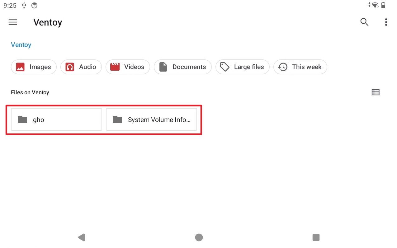
Click the EXPLORE button to browse the contents of the USB flash drive.
SD Card
SD card (Secure Digital Card) is a widely used portable storage medium, which has the characteristics of small size, large capacity, low power consumption and strong ease of use. It is often used in mobile phones, cameras, embedded devices and single-board computers to store system files, applications and data, and is one of the most mainstream storage solutions in modern mobile and embedded devices.
Hardware Interface
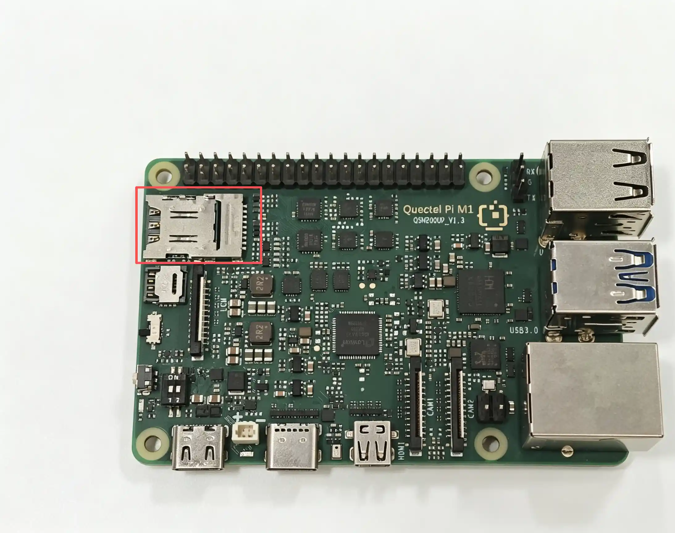
The Quectel Pi M1/L1 intelligent main control board is equipped with a micro SD + Nano SIM 2-in-1 card slot, which supports the SD 3.0 protocol.
Note: The upper slot is the micro SD card slot, and the lower one is the Nano SIM card slot.
Function Usage
System Recognition
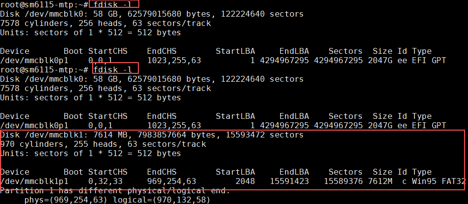
After inserting the SD card, you can use the following command to confirm whether the system has recognized the device:
fdisk -l
By comparing the output information before and after inserting the SD card, you can see that the system has successfully recognized the SD card:
Mounting and Unmounting
View the mount path:
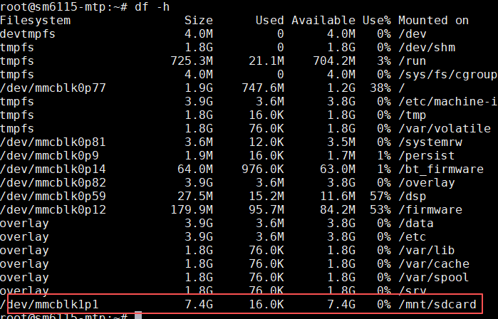
df -h
As shown below, the device has been automatically mounted to /mnt/sdcard:
View the files in the mount directory:
ls /mnt/sdcard
Mount to another directory:
sudo mkdir -p /media/sdcard
sudo mount /dev/mmcblk1p1 /media/sdcard
View the mount result:
ls /media/sdcard
Unmount after use:
sudo umount /media/sdcard
Tip: Unmount the SD card before removing it to prevent data corruption.
File Operations and Permissions
When ordinary users access the SD card, they may encounter the problem of insufficient permissions. You can change the ownership of the mount point with the following command:
sudo chown <username> /mnt/sdcard
sudo chmod 755 /mnt/sdcard
Replace <username> with the currently logged in username. After the modification, you can read and write files normally in the /mnt/sdcard directory.
ADC
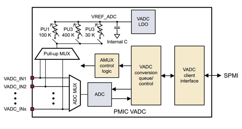
The ADC subsystem consists of a signal multiplexer and a voltage analog-to-digital converter (VADC). It is used to route internal and external analog signals to the VADC through multiplexing, and complete the conversion from analog quantity to digital quantity.
ADC Module Hardware Architecture Diagram
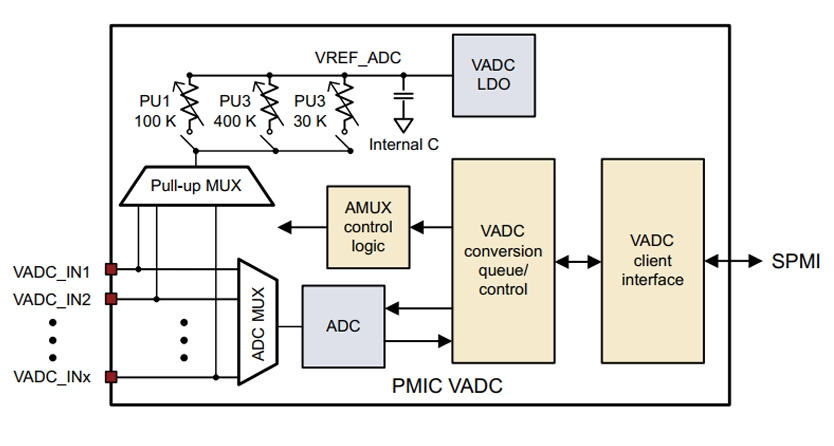
ADC Supported by M1 Module
The ADCs supported by the module are listed below:
Interface |
Pin Number |
Pin Name |
PM4250 Pin Number |
Voltage Domain |
MPM Interrupt |
Pin Description |
|---|---|---|---|---|---|---|
ADC |
128 |
ADC0 |
GPIO4 |
1.8 V |
- |
PMU_GPIO04 |
ADC |
185 |
ADC1 |
GPIO7 |
1.8 V |
- |
PMU_GPIO07 |
ADC Location
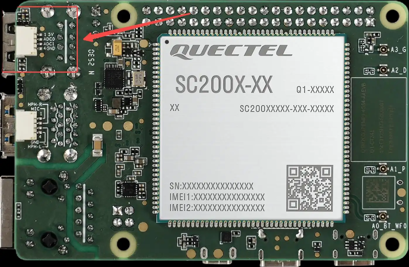
The location of the ADC interface on the smart main control board is shown in the figure below:
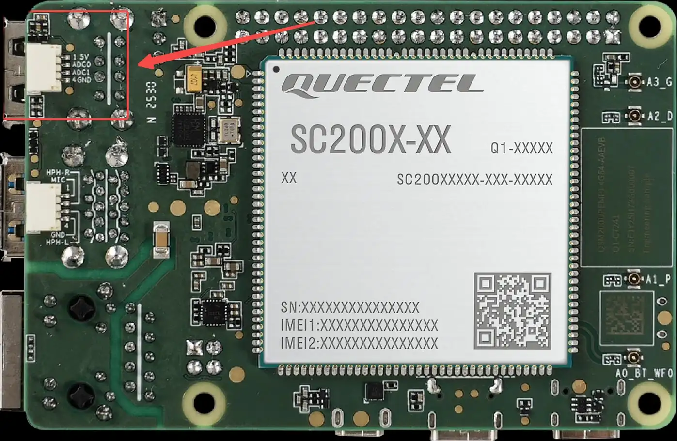
Location of ADC on the smart main control board
ADC Node Usage Example
The ADC node is mainly used to view the ADC value input to this node.
Usage Method
Use an adjustable DC power supply as the input signal source during testing:
Connect the positive pole of the power supply to the ADC0 or ADC1 pin.
Connect the power supply GND to the smart main control board GND.
The corresponding relationships and input characteristics of each channel are as follows:
ADC0:
Connected to GPIO4
Node:
in_voltage_adc_gpio4_inputSupported input voltage range: approximately 0~5.25 V
ADC1:
Connected to GPIO7
Node:
in_voltage_adc_gpio7_inputSupported input voltage range: approximately 0~5.25 V
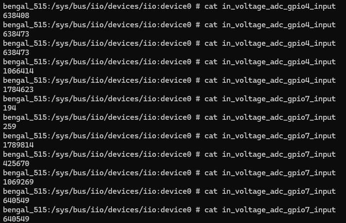
After setting the DC power supply to output the target voltage, you can read the ADC sampling result (unit: μV) with the following commands:
adb shell
cd /sys/bus/iio/devices/iio:device0
cat in_voltage_adc_gpio4_input
cat in_voltage_adc_gpio7_input
Test Code
The following sample code demonstrates the basic method of reading ADC voltage values in an application. The program reads the original ADC value (unit: μV) by accessing the node file corresponding to the ADC, and converts it to an integer for subsequent processing.
Click to expand/collapse: ADC reading test code (can be compiled with NDK by yourself)
#include <stdio.h>
#include <stdlib.h>
#include <unistd.h>
#include <fcntl.h>
#include <string.h>
#include <errno.h>
int main()
{
    int fd = -1;
    int adc_value;
    char buff[64] = {0};

    // Open the ADC node file (ADC0 corresponds to GPIO4)
    fd = open("/sys/bus/iio/devices/iio:device0/in_voltage_adc_gpio4_input", O_RDONLY);
    if(fd < 0){
        perror("open error\n");
        return fd;
    }

    // Read ADC value
    int n_read = read(fd, buff, sizeof(buff));
    if(n_read < 0) {
        perror("read error\n");
        close(fd);
        return -1;
    }
    // Convert the read string to an integer (unit: μV)
    adc_value = atol(buff);
    printf("read %d bytes, content: %s\n", n_read, buff);
    printf("ADC value: %d μV\n", adc_value);

    close(fd);
    return 0;
}
Code Description:
Use the
open()function to open the ADC node file/sys/bus/iio/devices/iio:device0/in_voltage_adc_gpio4_input.Use the
read()function to read the original ADC value (in string format, unit: μV).Use the
atol()function to convert the string to a long integer value.The unit of the read ADC value is microvolt (μV), which can be converted to a voltage value as needed.
Compilation and Execution:
# Compile with NDK
# Push the compiled executable file to the device and run it
adb push test_adc /data/local/tmp/test_adc
adb shell "chmod +x /data/local/tmp/test_adc"
adb shell "/data/local/tmp/test_adc"
Test Data
ADC Pin Specifications
The ADC pin definitions on the module are as follows:
Interface |
Module Pin Number |
Module Pin Name |
Module I/O |
NET Name (Multiplexing Function) |
Description |
|---|---|---|---|---|---|
ADC |
128 |
ADC0 |
I |
ADC0 |
1) Connector input voltage range: 0–5.25 V. |
ADC |
185 |
ADC1 |
I |
ADC1 |
Same electrical characteristics as ADC0 (0–5.25 V input range, RH = 18 kΩ, RL = 10 kΩ, ADC pin voltage = Vin × 10/28). |
ADC0 Test Data
Voltage Source |
ADC0 (μV) |
Theoretical Value (V) |
|---|---|---|
1.8 V |
638408 |
1.8 V×10/28 = 0.642857 |
3 V |
1066414 |
3 V×10/28 = 1.07143 |
5 V |
1784623 |
5 V×10/28 = 1.78571 |
ADC1 Test Data
Voltage Source |
ADC1 (μV) |
Theoretical Value (V) |
|---|---|---|
1.8 V |
640549 |
1.8 V×10/28 = 0.642857 |
3 V |
1069269 |
3 V×10/28 = 1.07143 |
5 V |
1789814 |
5 V×10/28 = 1.78571 |
ADC Supported by L1 Module
Interface |
Pin Number |
Pin Name |
PM4250 Pin Number |
Voltage Domain |
MPM Interrupt |
Pin Description |
|---|---|---|---|---|---|---|
ADC |
128 |
ADC0 |
GPIO4 |
1.8 V |
- |
PMU_GPIO04 |
ADC Location
The location of the ADC interface on the smart main control board is shown in the figure below:
ADC Node Usage Example
The ADC node is mainly used to view the ADC value input to this node.
Usage Method
Use an adjustable DC power supply as the input signal source during testing:
Connect the positive pole of the power supply to the ADC0 or ADC1 pin.
Connect the power supply GND to the smart main control board GND.
The corresponding relationships and input characteristics of each channel are as follows:
ADC0:
Connected to GPIO4
Node:
in_voltage_adc_gpio6_inputSupported input voltage range: approximately 0~5.25 V
After setting the DC power supply to output the target voltage, you can read the ADC sampling result (unit: μV) with the following commands:
adb shell
cd /sys/bus/iio/devices/iio:device0
cat in_voltage_adc_gpio6_input
ADC reading example output
Test Code
The following sample code demonstrates the basic method of reading ADC voltage values in an application. The program reads the original ADC value (unit: μV) by accessing the node file corresponding to the ADC, and converts it to an integer for subsequent processing.
Click to expand/collapse: ADC reading test code (can be compiled with NDK by yourself)
#include <stdio.h>
#include <stdlib.h>
#include <unistd.h>
#include <fcntl.h>
#include <string.h>
#include <errno.h>
int main()
{
    int fd = -1;
    int adc_value;
    char buff[64] = {0};

    // Open the ADC node file (ADC0 corresponds to GPIO4)
    fd = open("/sys/bus/iio/devices/iio:device0/in_voltage_adc_gpio6_input", O_RDONLY);
    if(fd < 0){
        perror("open error\n");
        return fd;
    }

    // Read ADC value
    int n_read = read(fd, buff, sizeof(buff));
    if(n_read < 0) {
        perror("read error\n");
        close(fd);
        return -1;
    }
    // Convert the read string to an integer (unit: μV)
    adc_value = atol(buff);
    printf("read %d bytes, content: %s\n", n_read, buff);
    printf("ADC value: %d μV\n", adc_value);

    close(fd);
    return 0;
}
Code Description:
Use the
open()function to open the ADC node file/sys/bus/iio/devices/iio:device0/in_voltage_adc_gpio6_input.Use the
read()function to read the original ADC value (in string format, unit: μV).Use the
atol()function to convert the string to a long integer value.The unit of the read ADC value is microvolt (μV), which can be converted to a voltage value as needed.
Compilation and Execution:
# Compile with NDK
# Push the compiled executable file to the device and run it
adb push test_adc /data/local/tmp/test_adc
adb shell "chmod +x /data/local/tmp/test_adc"
adb shell "/data/local/tmp/test_adc"
Test Data
ADC Pin Specifications
The ADC pin definitions on the module are as follows:
Interface |
Module Pin Number |
Module Pin Name |
Module I/O |
NET Name (Multiplexing Function) |
Description |
|---|---|---|---|---|---|
ADC |
128 |
ADC0 |
I |
ADC0 |
1) Connector input voltage range: 0–5.25 V. |
ADC0 Test Data
Voltage Source |
ADC0 (μV) |
Theoretical Value (V) |
|---|---|---|
1.8 V |
638408 |
1.8 V×10/28 = 0.642857 |
3 V |
1066414 |
3 V×10/28 = 1.07143 |
5 V |
1784623 |
5 V×10/28 = 1.78571 |
40-Pin Expansion
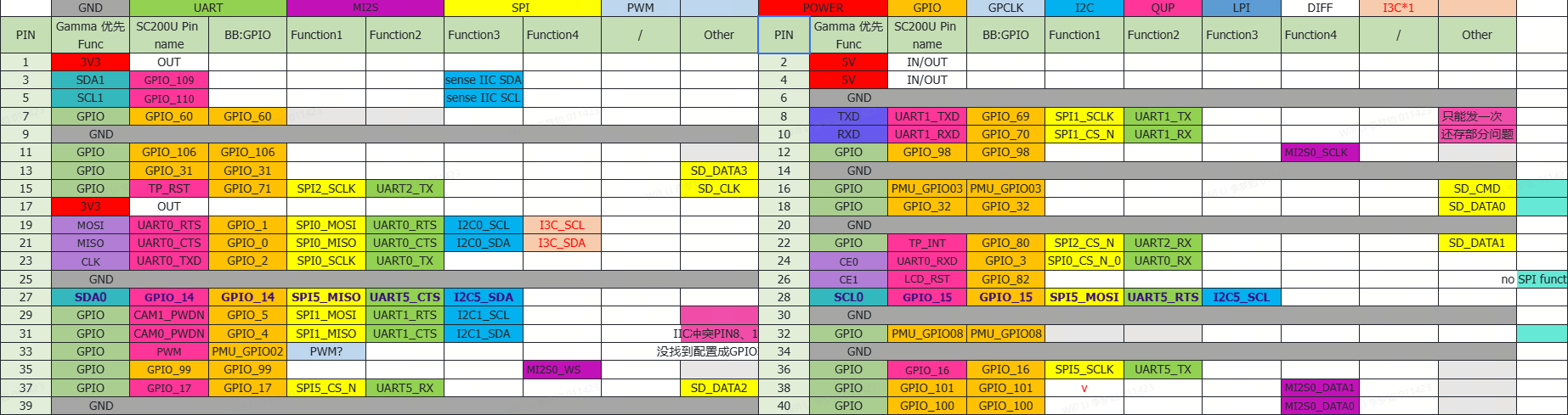
The Quectel Pi M1 smart main control board provides a standard 40-pin GPIO expansion interface, supporting multiple peripheral interfaces such as GPIO, I2C, SPI, UART, and PWM. The following describes how to test the functions of these interfaces.
Pin Definition
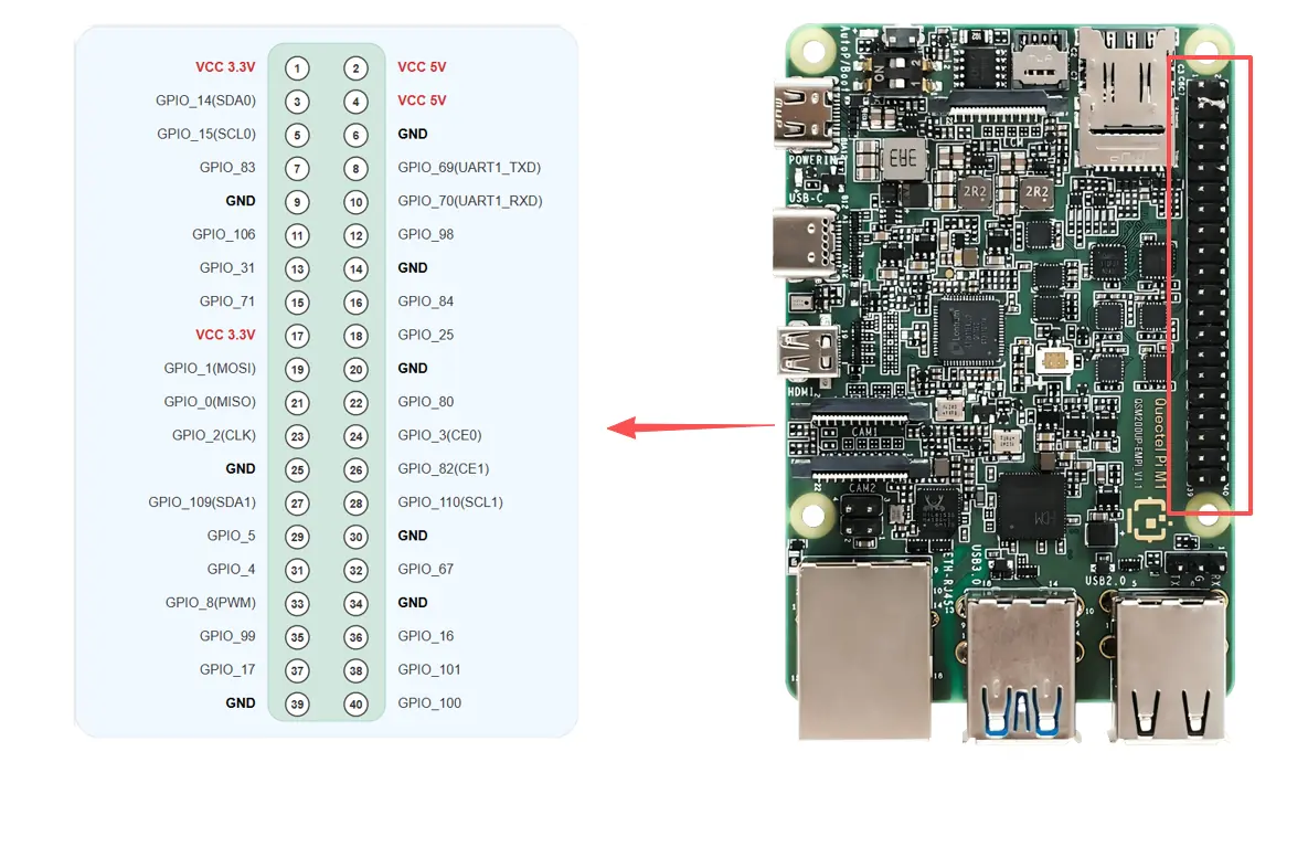
M1 GPIO pin correspondence list
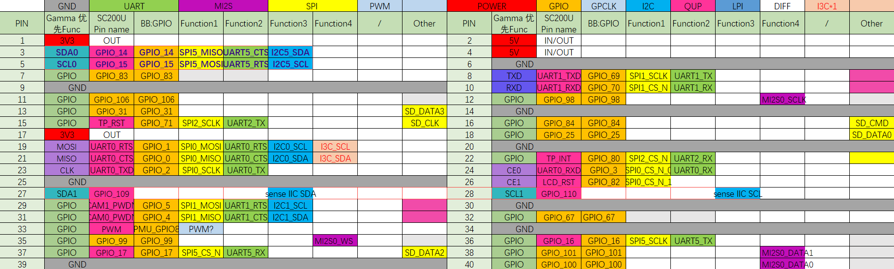
L1 GPIO pin correspondence list
GPIO Test
This section takes testing the pin7 of the M1 40-Pin as an example to demonstrate how to use the GPIO function. The gpio_num corresponding to pin7 is 83.
The GPIO test code for L1 can be reused, but you need to modify the GPIO value corresponding to the pin in the code.
Hardware Connection
Connection Method 1: Measure Voltage with a Multimeter
Connect the pin7 (GPIO_83) pin to the positive pole of the multimeter, and the pin6 (GND) pin to the negative pole of the multimeter. You can measure the voltage output by the pin through the multimeter to verify whether the GPIO function is normal.
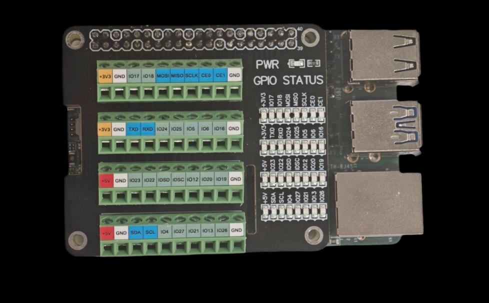
Connection Method 2: Use the GPIO Expansion Board Indicator
You can also test the GPIO high and low levels by plugging a Raspberry Pi 4B/3B GPIO expansion board into the 40-Pin expansion interface. This expansion board leads out each GPIO pin and is equipped with a corresponding indicator light. You can configure the GPIO pin to be tested as an output and connect it to the expansion board. When the GPIO outputs a high level, the small light turns on, and when it outputs a low level, the small light turns off, so that you can intuitively observe whether the GPIO level change meets the expectations. For more information about this expansion board, please refer to the GPIO terminal expansion board entry in the Accessories chapter.
Test Method
The following examples are based on the Android platform. The C code needs to be cross‑compiled using the NDK before it can be used. pin_control_sysfs source code (can be compiled with NDK on your own)
#include <stdio.h>
#include <stdlib.h>
#include <unistd.h>
#include <fcntl.h>
#include <string.h>
#include <errno.h>
// GPIO pin mapping table (SC200U Gamma Linux project)
typedef struct {
int pin;
int gpio_num;  // Linux sysfs GPIO number
} pin_map_t;
// GPIO mapping according to Bengal platform (consistent with Android project)
static const pin_map_t pin_mapping[] = {
{3, 494}, {5, 495}, {7, 481}, {8, 467}, {10, 468}, {11, 504}, {12, 496}, {13, 429},
{15, 469}, {16, 482}, {18, 423}, {19, 399}, {21, 398}, {22, 478}, {23, 400}, {24, 401},
{26, 480}, {27, 412}, {28, 413}, {29, 403}, {31, 402}, {32, 465}, {33, 396}, {35, 497},
{36, 414}, {37, 415}, {38, 499}, {40, 498}
};
#define PIN_COUNT (sizeof(pin_mapping) / sizeof(pin_map_t))
/**
 * Get GPIO mapping information according to pin number
 */
const pin_map_t* get_pin_info(int pin) {
for (int i = 0; i < PIN_COUNT; i++) {
if (pin_mapping[i].pin == pin) {
return &pin_mapping[i];
}
}
return NULL;
}
/**
 * Export GPIO to sysfs
 */
int export_gpio(int gpio_num) {
char path[64];
int fd;
// Check if GPIO has been exported
snprintf(path, sizeof(path), "/sys/class/gpio/gpio%d", gpio_num);
if (access(path, F_OK) == 0) {
return 0;  // Already exported
}
// Export GPIO
    fd = open("/sys/class/gpio/export", O_WRONLY);
if (fd < 0) {
printf("Failed to open /sys/class/gpio/export: %s\n", strerror(errno));
return -1;
}
char gpio_str[8];
snprintf(gpio_str, sizeof(gpio_str), "%d", gpio_num);
if (write(fd, gpio_str, strlen(gpio_str)) < 0) {
// If the GPIO has been exported, an error will be returned when writing, ignore this non-fatal issue
if (errno != EBUSY) {
printf("Failed to export GPIO%d: %s\n", gpio_num, strerror(errno));
close(fd);
return -1;
}
}
close(fd);
usleep(100000);  // Delay 100ms, wait for sysfs node creation to complete
return 0;
}
/**
 * Unexport GPIO from sysfs
 */
int unexport_gpio(int gpio_num) {
int fd;

    fd = open("/sys/class/gpio/unexport", O_WRONLY);
if (fd < 0) {
return -1;
}
char gpio_str[8];
snprintf(gpio_str, sizeof(gpio_str), "%d", gpio_num);
write(fd, gpio_str, strlen(gpio_str));
close(fd);
return 0;
}
/**
 * Set GPIO direction
 */
int set_gpio_direction(int gpio_num, const char *direction) {
char path[64];
int fd;
snprintf(path, sizeof(path), "/sys/class/gpio/gpio%d/direction", gpio_num);
    fd = open(path, O_WRONLY);
if (fd < 0) {
printf("Failed to open %s: %s\n", path, strerror(errno));
return -1;
}
if (write(fd, direction, strlen(direction)) < 0) {
printf("Failed to set GPIO%d direction: %s\n", gpio_num, strerror(errno));
close(fd);
return -1;
}
close(fd);
return 0;
}
/**
 * Set GPIO value
 */
int set_gpio_value(int gpio_num, int value) {
char path[64];
int fd;
snprintf(path, sizeof(path), "/sys/class/gpio/gpio%d/value", gpio_num);
    fd = open(path, O_WRONLY);
if (fd < 0) {
printf("Failed to open %s: %s\n", path, strerror(errno));
return -1;
}
char value_str[2];
snprintf(value_str, sizeof(value_str), "%d", value);
if (write(fd, value_str, 1) < 0) {
printf("Failed to set GPIO%d value: %s\n", gpio_num, strerror(errno));
close(fd);
return -1;
}
close(fd);
return 0;
}
/**
 * Read GPIO value
 */
int get_gpio_value(int gpio_num, int *value) {
char path[64];
int fd;
char val[2];
snprintf(path, sizeof(path), "/sys/class/gpio/gpio%d/value", gpio_num);
    fd = open(path, O_RDONLY);
if (fd < 0) {
printf("Failed to open %s: %s\n", path, strerror(errno));
return -1;
}
if (read(fd, val, 1) < 0) {
printf("Failed to read GPIO%d: %s\n", gpio_num, strerror(errno));
close(fd);
return -1;
}
close(fd);
*value = (val[0] == '1') ? 1 : 0;
return 0;
}
/**
 * Use sysfs to control GPIO
 * action: 0=pull low, 1=pull high, 2=read
 */
int control_gpio_sysfs(int gpio_num, int action) {
// Ensure GPIO is exported
if (export_gpio(gpio_num) < 0) {
return -1;
}
if (action == 0 || action == 1) {
// Set direction to output
if (set_gpio_direction(gpio_num, "out") < 0) {
return -1;
}
// Set value
if (set_gpio_value(gpio_num, action) < 0) {
return -1;
}
printf("✓ GPIO%d has been set to %s level\n", gpio_num, action ? "high" : "low");
// Verify whether the setting takes effect
usleep(50000);
int verify_value;
if (get_gpio_value(gpio_num, &verify_value) == 0) {
printf("  Verification: GPIO%d actual status: %s level (value: %d)\n",
                   gpio_num, verify_value ? "high" : "low", verify_value);
}
} else if (action == 2) {
// Read GPIO value
int value;
if (get_gpio_value(gpio_num, &value) == 0) {
printf("✓ GPIO%d current status: %s level (value: %d)\n",
                   gpio_num, value ? "high" : "low", value);
} else {
return -1;
}
}
return 0;
}
/**
 * Read all pin statuses
 */
int read_all_pins() {
printf("========================================\n");
printf("=== Read all pin statuses ===\n");
printf("========================================\n");
int success_count = 0;
for (int i = 0; i < PIN_COUNT; i++) {
printf("pin%d (GPIO%d): ", pin_mapping[i].pin, pin_mapping[i].gpio_num);
fflush(stdout);
if (control_gpio_sysfs(pin_mapping[i].gpio_num, 2) == 0) {
            success_count++;
} else {
printf("✗ Read failed\n");
}
}
printf("========================================\n");
printf("Successfully read %d/%lu pins\n", success_count, PIN_COUNT);
printf("========================================\n");
return 0;
}
/**
 * Control all pins
 */
int control_all_pins(int action) {
printf("========================================\n");
printf("Start to set all pins to %s level...\n", action ? "high" : "low");
printf("========================================\n");
int success_count = 0;
for (int i = 0; i < PIN_COUNT; i++) {
printf("pin%d (GPIO%d): ", pin_mapping[i].pin, pin_mapping[i].gpio_num);
fflush(stdout);
if (control_gpio_sysfs(pin_mapping[i].gpio_num, action) == 0) {
            success_count++;
} else {
printf("✗ Control failed\n");
}
}
printf("========================================\n");
printf("Successfully controlled %d/%lu pins\n", success_count, PIN_COUNT);
printf("========================================\n");
return (success_count == PIN_COUNT) ? 0 : 1;
}
/**
 * Display help information
 */
void show_help(const char *prog_name) {
printf("Usage: %s <pin_number|all> <up|down|get>\n", prog_name);
printf("Example: %s pin3 up     # Pull pin3 high\n", prog_name);
printf("Example: %s pin5 down   # Pull pin5 low\n", prog_name);
printf("Example: %s pin7 get    # Read pin7\n", prog_name);
printf("Example: %s all up      # Pull all pins high\n", prog_name);
printf("Example: %s all down    # Pull all pins low\n", prog_name);
printf("Example: %s all get     # Read all pin statuses\n", prog_name);
printf("\nSupported pins:\n");
for (int i = 0; i < PIN_COUNT; i++) {
printf("pin%d(GPIO%d)  ", pin_mapping[i].pin, pin_mapping[i].gpio_num);
if ((i + 1) % 4 == 0) printf("\n");
}
printf("\n");
}
/**
 * Main function
 */
int main(int argc, char *argv[]) {
if (argc < 3) {
show_help(argv[0]);
return 1;
}
char *pin_str = argv[1];
char *action_str = argv[2];
// Parse action parameter
int action;
if (strcmp(action_str, "up") == 0) {
        action = 1;
} else if (strcmp(action_str, "down") == 0) {
        action = 0;
} else if (strcmp(action_str, "get") == 0) {
        action = 2;
} else {
printf("Error: Action must be up, down or get\n");
return 1;
}
// Process all command
if (strcmp(pin_str, "all") == 0) {
if (action == 2) {
return read_all_pins();
} else {
return control_all_pins(action);
}
}
// Parse pin number
int pin;
if (sscanf(pin_str, "pin%d", &pin) != 1) {
printf("Error: Invalid pin format, please use pin3, pin5, etc.\n");
return 1;
}
const pin_map_t *pin_info = get_pin_info(pin);
if (pin_info == NULL) {
printf("Error: Unsupported pin pin%d\n", pin);
return 1;
}
printf("Controlling pin%d (GPIO%d)...\n", pin, pin_info->gpio_num);
return control_gpio_sysfs(pin_info->gpio_num, action);
}
Push the cross‑compiled executable file to the development board and grant permissions:
adb push <local storage path>/pin_control_sysfs /data/local/tmp/pin_control_sysfs
adb shell "chmod +x /data/local/tmp/pin_control_sysfs"
adb shell "ls -lh /data/local/tmp/pin_control_sysfs"
Enter the device-side shell and run the tool to view the usage:
adb shell
cd /data/local/tmp
./pin_control_sysfs
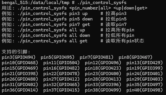
After running, the available commands and the supported 40-pin pin mapping will be printed. An example output is as follows:
Common operation examples:
Pull a single pin high:
./pin_control_sysfs pin7 upPull a single pin low:
./pin_control_sysfs pin7 downRead a single pin:
./pin_control_sysfs pin7 getOperate all pins:
./pin_control_sysfs all up | all down | all get
Tip: When running, ensure that the target pin is not occupied by other functions (such as I2C/SPI/UART). It is recommended to confirm whether the level change meets expectations through the expansion board indicator light or a multimeter first.
I2C Test
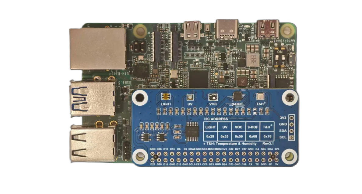
Pin3 and pin5 of the 40-pin interface are the default I2C data and clock pins. To test the I2C interface, we need to connect an external I2C device. Here we use the Waveshare Environment Sensor Expansion Board, and the corresponding device node is /dev/i2c-1.
Test Preparation
IC |
I2C Addr |
ID Reg |
Expected ID Return Value |
|---|---|---|---|
WSL25911FN |
0x29 |
0x12 |
0x50 |
BME280 |
0x76 |
0xD0 |
0x60 |
MPU9250 |
0x68 |
0x75 |
0x71 |
LTR390-UV-1 |
0x53 |
0x06 |
0xB2 |
PS: When reading the ID register for WSL25911FN here, the command bit (i.e. 0xA0) needs to be included, which means that the register 0x12 is actually written as 0xA0 | 0x12 = 0xB2 during access, and this is not required for others.
This test uses the Waveshare Environment Sensor Expansion Board, connected via the 40-pin interface.
Hardware connection diagram:
Test Method
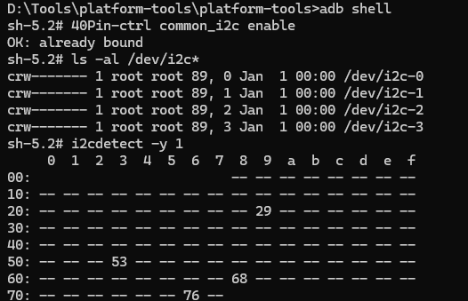
adb shell #Enter ADB shell
ls -al /dev/i2c* #Check if I2C-1 exists in the corresponding directory
i2cdetect -y 1   #Check how many devices are connected to the corresponding I2C bus
I2C Read/Write
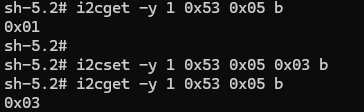
i2cget -y 1 0x53 0x05 b #Read the value of register 0x05 of the device with address 0x53 on i2c1, the size is one byte
i2cset -y 1 0x53 0x05 0x03 b #Set the value of register 0x05 of the device with address 0x53 on i2c1 to 0x03, the size is one byte
SPI Test
The device chip select nodes corresponding to the SPI function in the 40-pin interface are /dev/spidev0.0 and /dev/spidev0.1. Enter the following content in adb to view these nodes:
adb shell "ls /dev/spidev*"
Waveshare OLED Display Test (cs0 and cs1)
Please wire according to the following table:
OLED Pin |
Should Be Connected To |
SC200U Physical Pin |
Remarks |
|---|---|---|---|
VCC |
3.3V power supply |
Pin1 or Pin17 |
Must be 3.3V |
GND |
Ground |
Any GND such as Pin6/9/14 |
Common ground |
DIN/MOSI |
SPI data |
Pin19 |
SPI_MOSI |
CLK/SCK |
SPI clock |
Pin23 |
SPI_CLK |
CS/CE |
Chip select |
Pin24/Pin26 |
SPI_CE0/SPI_CE1 |
D/C |
Data/Command |
Pin22 |
GPIO80 |
RES/RST |
Reset |
Pin18 |
GPIO25 |
Hardware connection diagram:
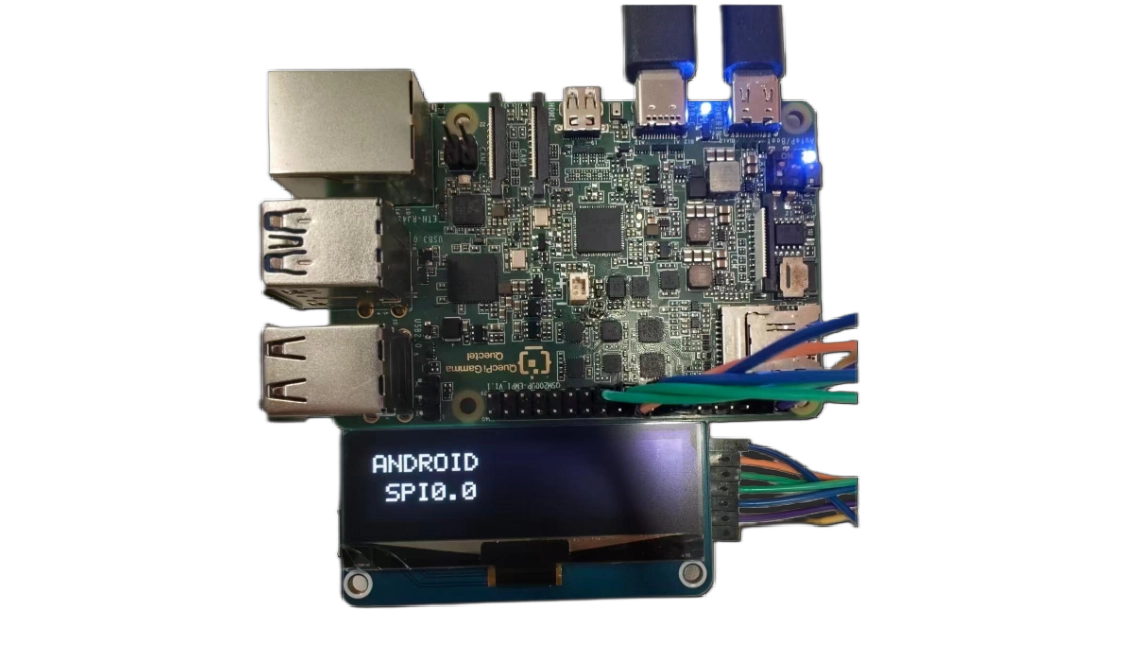
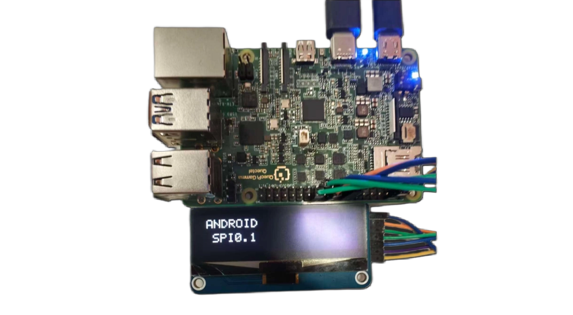
Execution Steps:
Create the source file
Create a new test_spi.c file with the following content:
test_spi source code (you can use NDK or cross-compile by yourself)
/*
 * Test both CE0 and CE1 - requires manual wire switching
 * This helps verify which CS pin your OLED is connected to
 * Enhanced with text display and FPS performance test
 */#include <stdio.h>#include <stdlib.h>#include <stdint.h>#include <string.h>#include <unistd.h>#include <fcntl.h>#include <sys/ioctl.h>#include <linux/spi/spidev.h>#include <time.h>#define GPIO_BASE   398#define GPIO_RST    (GPIO_BASE + 25)#define GPIO_DC     (GPIO_BASE + 80)#define SPI_MODE    SPI_MODE_3#define SPI_SPEED   8000000#define OLED_WIDTH  128#define OLED_HEIGHT 32#define OLED_PAGES  4// Complete 5x7 fontstatic const uint8_t font_5x7[][5] = {{0x00, 0x00, 0x00, 0x00, 0x00}, // Space{0x3E, 0x51, 0x49, 0x45, 0x3E}, // 0{0x00, 0x42, 0x7F, 0x40, 0x00}, // 1{0x42, 0x61, 0x51, 0x49, 0x46}, // 2{0x21, 0x41, 0x45, 0x4B, 0x31}, // 3{0x18, 0x14, 0x12, 0x7F, 0x10}, // 4{0x27, 0x45, 0x45, 0x45, 0x39}, // 5{0x3C, 0x4A, 0x49, 0x49, 0x30}, // 6{0x01, 0x71, 0x09, 0x05, 0x03}, // 7{0x36, 0x49, 0x49, 0x49, 0x36}, // 8{0x06, 0x49, 0x49, 0x29, 0x1E}, // 9{0x7E, 0x11, 0x11, 0x11, 0x7E}, // A{0x7F, 0x49, 0x49, 0x49, 0x36}, {0x3E, 0x41, 0x41, 0x41, 0x22}, // B C{0x7F, 0x41, 0x41, 0x22, 0x1C}, {0x7F, 0x49, 0x49, 0x49, 0x41}, // D E{0x7F, 0x09, 0x09, 0x09, 0x01}, {0x3E, 0x41, 0x49, 0x49, 0x7A}, // F G{0x7F, 0x08, 0x08, 0x08, 0x7F}, {0x00, 0x41, 0x7F, 0x41, 0x00}, // H I{0x20, 0x40, 0x41, 0x3F, 0x01}, {0x7F, 0x08, 0x14, 0x22, 0x41}, // J K{0x7F, 0x40, 0x40, 0x40, 0x40}, {0x7F, 0x02, 0x0C, 0x02, 0x7F}, // L M{0x7F, 0x04, 0x08, 0x10, 0x7F}, {0x3E, 0x41, 0x41, 0x41, 0x3E}, // N O{0x7F, 0x09, 0x09, 0x09, 0x06}, {0x3E, 0x41, 0x51, 0x21, 0x5E}, // P Q{0x7F, 0x09, 0x19, 0x29, 0x46}, {0x46, 0x49, 0x49, 0x49, 0x31}, // R S{0x01, 0x01, 0x7F, 0x01, 0x01}, {0x3F, 0x40, 0x40, 0x40, 0x3F}, // T U{0x1F, 0x20, 0x40, 0x20, 0x1F}, {0x3F, 0x40, 0x38, 0x40, 0x3F}, // V W{0x63, 0x14, 0x08, 0x14, 0x63}, {0x07, 0x08, 0x70, 0x08, 0x07}, // X Y{0x61, 0x51, 0x49, 0x45, 0x43}, // Z{0x08, 0x08, 0x08, 0x08, 0x08}, // -{0x00, 0x36, 0x36, 0x00, 0x00}, // :{0x00, 0x60, 0x60, 0x00, 0x00}, // .};static int char_to_index(char c) {if (c == ' ') return 0;if (c >= '0' && c <= '9') return 1 + (c - '0');if (c >= 'A' && c <= 'Z') return 11 + (c - 'A');if (c >= 'a' && c <= 'z') return 11 + (c - 'a');if (c == '-') return 37;if (c == ':') return 38;if (c == '.') return 39;return 0;}int gpio_write(int gpio, int value);void oled_quick_test(const char *device, const char *name);int main() {printf("\n╔════════════════════════════════════════════════════════╗\n");printf("║  Chip Select Pin Comparison Tool                      ║\n");printf("╚════════════════════════════════════════════════════════╝\n");printf("\nThis tool helps identify which CS pin is connected.\n");printf("\nInstruction:\n");printf("  1. Connect OLED CS to Pin24 first\n");printf("  2. Run test - should see display\n");printf("  3. Move OLED CS to Pin26\n");printf("  4. Run test again - should see display\n");printf("\n");char choice;printf("Which pin is your OLED CS currently connected to?\n");printf("  [0] Pin24 (CE0)\n");printf("  [1] Pin26 (CE1)\n");printf("Choice: ");scanf(" %c", &choice);if (choice == '0') {printf("\nTesting CE0 (Pin24)...\n");oled_quick_test("/dev/spidev0.0", "CE0-PIN24");} else if (choice == '1') {printf("\nTesting CE1 (Pin26)...\n");oled_quick_test("/dev/spidev0.1", "CE1-PIN26");} else {printf("Invalid choice\n");return 1;}return 0;}void oled_quick_test(const char *device, const char *name) {// Display bufferstatic uint8_t buffer[OLED_PAGES][OLED_WIDTH];// Simple GPIO functionsint gpio_export(int gpio) {int fd = open("/sys/class/gpio/export", O_WRONLY);if (fd < 0) return -1;char buf[10];snprintf(buf, sizeof(buf), "%d", gpio);write(fd, buf, strlen(buf));close(fd);usleep(100000);return 0;}int gpio_set_dir(int gpio) {char path[50];snprintf(path, sizeof(path), "/sys/class/gpio/gpio%d/direction", gpio);int fd = open(path, O_WRONLY);if (fd < 0) return -1;write(fd, "out", 3);close(fd);return 0;}int gpio_write(int gpio, int value) {char path[50];snprintf(path, sizeof(path), "/sys/class/gpio/gpio%d/value", gpio);int fd = open(path, O_WRONLY);if (fd < 0) return -1;char buf[2] = {value ? '1' : '0', 0};write(fd, buf, 1);close(fd);return 0;}void send_cmd(int fd, uint8_t cmd) {gpio_write(GPIO_DC, 0);write(fd, &cmd, 1);usleep(1000);}void set_pixel(int x, int y, int color) {if (x >= 0 && x < OLED_WIDTH && y >= 0 && y < OLED_HEIGHT) {int page = y / 8;int bit = y % 8;if (color)
                buffer[page][x] |= (1 << bit);else
                buffer[page][x] &= ~(1 << bit);}}void draw_char(int x, int y, char c) {int idx = char_to_index(c);for (int col = 0; col < 5; col++) {uint8_t data = font_5x7[idx][col];for (int row = 0; row < 8; row++) {if (data & (1 << row)) {set_pixel(x + col, y + row, 1);}}}}void draw_text(int x, int y, const char *text) {int cursor = x;while (*text) {draw_char(cursor, y, *text);
            cursor += 6;
            text++;}}void clear_buffer() {memset(buffer, 0, OLED_PAGES * OLED_WIDTH);}void display_buffer(int fd) {for (int page = 0; page < OLED_PAGES; page++) {send_cmd(fd, 0xB0 + page);send_cmd(fd, 0x04);send_cmd(fd, 0x10);gpio_write(GPIO_DC, 1);write(fd, buffer[page], OLED_WIDTH);}}// Initialize GPIOgpio_export(GPIO_RST);gpio_export(GPIO_DC);usleep(200000);gpio_set_dir(GPIO_RST);gpio_set_dir(GPIO_DC);// Open SPIprintf("  Opening %s...\n", device);int spi_fd = open(device, O_RDWR);if (spi_fd < 0) {perror("  ERROR: Cannot open device");printf("  → %s is NOT working or OLED not connected\n", name);return;}printf("  ✓ Device opened\n");// Configure SPIuint8_t mode = SPI_MODE;uint32_t speed = SPI_SPEED;ioctl(spi_fd, SPI_IOC_WR_MODE, &mode);ioctl(spi_fd, SPI_IOC_WR_MAX_SPEED_HZ, &speed);// Reset OLEDprintf("  Resetting OLED...\n");gpio_write(GPIO_RST, 0);usleep(50000);gpio_write(GPIO_RST, 1);usleep(50000);// Initialize OLEDprintf("  Initializing OLED...\n");send_cmd(spi_fd, 0xAE);send_cmd(spi_fd, 0x04); send_cmd(spi_fd, 0x10); send_cmd(spi_fd, 0x40);send_cmd(spi_fd, 0x81); send_cmd(spi_fd, 0xFF);send_cmd(spi_fd, 0xA1); send_cmd(spi_fd, 0xA6);send_cmd(spi_fd, 0xA8); send_cmd(spi_fd, 0x1F);send_cmd(spi_fd, 0xC8);send_cmd(spi_fd, 0xD3); send_cmd(spi_fd, 0x00);send_cmd(spi_fd, 0xD5); send_cmd(spi_fd, 0xF0);send_cmd(spi_fd, 0xD8); send_cmd(spi_fd, 0x05);send_cmd(spi_fd, 0xD9); send_cmd(spi_fd, 0xC2);send_cmd(spi_fd, 0xDA); send_cmd(spi_fd, 0x12);send_cmd(spi_fd, 0xDB); send_cmd(spi_fd, 0x08);send_cmd(spi_fd, 0xAF);printf("  ✓ OLED initialized\n");// Test 1: Display "USING: CE0" or "USING: CE1"printf("\n  [Test 1] Displaying chip select info...\n");clear_buffer();draw_text(10, 4, "USING:");if (strstr(name, "CE0")) {draw_text(25, 16, "CE0");} else {draw_text(25, 16, "CE1");}display_buffer(spi_fd);printf("  ✓ Screen showing: USING %s\n", strstr(name, "CE0") ? "CE0" : "CE1");sleep(3);// Test 2: Fill whiteprintf("\n  [Test 2] Filling screen WHITE...\n");memset(buffer, 0xFF, OLED_PAGES * OLED_WIDTH);display_buffer(spi_fd);printf("  ✓ Screen should be WHITE\n");sleep(2);// Test 3: Blink testprintf("\n  [Test 3] Blink test (5 times)...\n");for (int i = 0; i < 5; i++) {// Whitememset(buffer, 0xFF, OLED_PAGES * OLED_WIDTH);display_buffer(spi_fd);usleep(200000);// Blackmemset(buffer, 0x00, OLED_PAGES * OLED_WIDTH);display_buffer(spi_fd);usleep(200000);printf("    Blink %d/5\n", i + 1);}printf("  ✓ Blink test complete\n");// Test 4: FPS Performance Testprintf("\n  [Test 4] FPS Performance Test...\n");printf("  Running 100 frame updates...\n");struct timespec start, end;clock_gettime(CLOCK_MONOTONIC, &start);for (int frame = 0; frame < 100; frame++) {// Generate test patternfor (int page = 0; page < OLED_PAGES; page++) {for (int x = 0; x < OLED_WIDTH; x++) {
                buffer[page][x] = (x + frame) & 0xFF;}}display_buffer(spi_fd);}clock_gettime(CLOCK_MONOTONIC, &end);double elapsed = (end.tv_sec - start.tv_sec) +
                     (end.tv_nsec - start.tv_nsec) / 1000000000.0;double fps = 100.0 / elapsed;printf("  ✓ Performance: %.1f FPS\n", fps);// Display FPS result on screenclear_buffer();draw_text(10, 4, "FPS TEST");char fps_str[20];snprintf(fps_str, sizeof(fps_str), "%.1f FPS", fps);draw_text(20, 16, fps_str);display_buffer(spi_fd);printf("  ✓ FPS result displayed on screen\n");sleep(3);// Test 5: CS Pin Functionality Testprintf("\n  [Test 5] CS Pin Functionality Test...\n");printf("  This test verifies CS pin actually controls the device\n");// Step 1: Display number 1printf("  Step 1: Displaying pattern 1...\n");clear_buffer();draw_text(15, 4, "PATTERN");draw_text(50, 16, "1");display_buffer(spi_fd);sleep(2);// Step 2: Try to update through the OTHER CS (should fail if CS works)printf("  Step 2: Trying to update via OTHER CS...\n");const char *other_device = strstr(name, "CE0") ? "/dev/spidev0.1" : "/dev/spidev0.0";const char *other_name = strstr(name, "CE0") ? "CE1" : "CE0";int other_fd = open(other_device, O_RDWR);if (other_fd >= 0) {uint8_t mode = SPI_MODE;uint32_t speed = SPI_SPEED;ioctl(other_fd, SPI_IOC_WR_MODE, &mode);ioctl(other_fd, SPI_IOC_WR_MAX_SPEED_HZ, &speed);// Try to display pattern 2 via other CSclear_buffer();draw_text(15, 4, "PATTERN");draw_text(50, 16, "2");for (int page = 0; page < OLED_PAGES; page++) {send_cmd(other_fd, 0xB0 + page);send_cmd(other_fd, 0x04);send_cmd(other_fd, 0x10);gpio_write(GPIO_DC, 1);write(other_fd, buffer[page], OLED_WIDTH);}close(other_fd);printf("  Sent update via %s (other CS)\n", other_name);sleep(2);printf("\n  ╔════════════════════════════════════════════════╗\n");printf("  ║ CHECK SCREEN: Still showing '1' or changed to '2'? ║\n");printf("  ╚════════════════════════════════════════════════╝\n");printf("\n  If still showing '1': CS pin is WORKING correctly ✓\n");printf("  If changed to '2': CS pin NOT working (both CS active) ✗\n\n");sleep(2);}// Step 3: Update back via correct CSprintf("  Step 3: Updating via correct CS (%s)...\n", name);clear_buffer();draw_text(15, 4, "BACK TO");draw_text(50, 16, "1");display_buffer(spi_fd);printf("  ✓ Should see pattern 1 again\n");sleep(2);// Test 6: FPS result summaryprintf("\n  [Test 6] Final Summary...\n");clear_buffer();draw_text(30, 4, name);char summary_str[20];snprintf(summary_str, sizeof(summary_str), "%.1fFPS", fps);draw_text(20, 16, summary_str);display_buffer(spi_fd);printf("  ✓ Summary displayed\n");sleep(3);// Clear screenclear_buffer();display_buffer(spi_fd);close(spi_fd);printf("\n======================================================================\n");printf("  %s Test Complete!\n", name);printf("======================================================================\n");printf("  CS Pin Test Result:\n");printf("    If screen didn't change to '2' in Step 2:\n");printf("      → CS pin is working correctly ✓\n");printf("    If screen changed to '2':\n");printf("      → CS pin might not be controlling the device ✗\n");printf("      → Both CS pins may be active simultaneously\n");printf("\n  Performance: %.1f FPS\n", fps);printf("======================================================================\n");}
adb root
adb push "D:\tools\40pin android\test_android_spi" /data/local/tmp/test_android_spi
adb shell "chmod +x /data/local/tmp/test_android_spi"
adb shell
cd /data/local/tmp/
./test_android_spi
After the program runs, you will be prompted to select the SPI device:
Select 0: Use
/dev/spidev0.0(CE0, Pin24)Select 1: Use
/dev/spidev0.1(CE1, Pin26)
Please select the corresponding device according to the actual wiring situation (select 0 if the CS/CE pin is connected to pin24, and select 1 if it is connected to pin26).
Test Results:
After the program is executed, the following tests will be carried out in sequence:
╔══════════════════════════════════════════════════════╗
║        Android SPI OLED Test Program                ║
║        Compatible with Android devices              ║
╚══════════════════════════════════════════════════════╝

Select SPI device:
  [0] /dev/spidev0.0 (CE0, Pin24)
  [1] /dev/spidev0.1 (CE1, Pin26)
  [c] Custom device path
Selection: 1

Device in use: /dev/spidev0.1

Initializing GPIO...
  ✓ GPIO initialization successful

Opening SPI device: /dev/spidev0.1
  ✓ SPI device opened and configured
    - Mode: 3
    - Speed: 2000000 Hz
    - Bit width: 8 bits

Initializing OLED...
  Resetting OLED...
  Sending initialization commands...
  ✓ OLED initialization completed

━━━━━━━━━━━━━━━━━━━━━━━━━━━━━━━━━━━━━━━━━━━━━━
  Starting test sequence: SPI0.1
━━━━━━━━━━━━━━━━━━━━━━━━━━━━━━━━━━━━━━━━━━━━━━

[Test 1] Displaying device information...
  ✓ The screen should display: ANDROID SPI0.1

[Test 2] All-white screen test...
  ✓ The screen should be fully white

[Test 3] Blink test (5 times)...
    Blink 1/5
    Blink 2/5
    Blink 3/5
    Blink 4/5
    Blink 5/5
  ✓ Blink test completed

[Test 4] FPS performance test...
  Running 100 frame updates...
  ✓ Performance: 40.3 FPS (Time elapsed: 2.48 seconds)
  ✓ FPS result has been displayed

[Test 5] Pattern test...
  Pattern 1: Horizontal stripes
  Pattern 2: Vertical stripes
  Pattern 3: Checkerboard
  ✓ Pattern test completed

[Test 6] Test summary...
  ✓ Summary has been displayed
Test Instructions:
Test 1: Verify that the OLED can display text information normally
Test 2: Verify the full-screen display function of the OLED
Test 3: Verify the OLED refresh function through the blink test
Test 4: Test SPI communication performance (FPS value)
Test 5: Test the display function of different patterns
Test 6: Display test summary information
If all test items show a √ mark, it indicates that the SPI communication and OLED functions are all normal.
UART Test
Among the 40-pin interface,pin8 and pin10 are configured with UART function by default, and the corresponding device node is /dev/ttyHS0.
View serial port devices
You can use the following command to view all serial port devices in the system:
```Bash
ls /dev/tty*
UART Loopback Test
This test verifies whether the serial port transceiving function is normal by short-circuiting pin8 and pin10.
Hardware connection: Short-circuit pin8 (TX) and pin10 (RX) of the 40-pin connector.
Execution Step: Create the source file
Create a new uart_loopback.c file with the following content:
uart_loopback source code (you can use NDK or cross-compile by yourself)
#include <stdio.h>#include <stdlib.h>#include <string.h>#include <unistd.h>#include <fcntl.h>#include <termios.h>#include <errno.h>#include <signal.h>// Global variable for signal handlingstatic int serial_fd = -1;static volatile int running = 1;// Signal handler functionvoid signal_handler(int sig) {printf("\nUser interrupted the test\n");
    running = 0;if (serial_fd >= 0) {close(serial_fd);printf("Serial port closed\n");}exit(0);}// Configure serial port parametersint configure_serial(int fd, int baudrate) {struct termios tty;if (tcgetattr(fd, &tty) != 0) {printf("Failed to get serial port attributes: %s\n", strerror(errno));return -1;}// Set baud ratespeed_t speed;switch (baudrate) {case 9600:   speed = B9600;   break;case 19200:  speed = B19200;  break;case 38400:  speed = B38400;  break;case 57600:  speed = B57600;  break;case 115200: speed = B115200; break;case 230400: speed = B230400; break;default:     speed = B115200; break;}cfsetospeed(&tty, speed);cfsetispeed(&tty, speed);// Configure serial port parameters
    tty.c_cflag &= ~PARENB;        // No parity check
    tty.c_cflag &= ~CSTOPB;        // 1 stop bit
    tty.c_cflag &= ~CSIZE;         // Clear data bit setting
    tty.c_cflag |= CS8;            // 8 data bits
    tty.c_cflag &= ~CRTSCTS;       // Disable hardware flow control
    tty.c_cflag |= CREAD | CLOCAL; // Enable reception and local connection// Configure input mode
    tty.c_iflag &= ~(IXON | IXOFF | IXANY); // Disable software flow control
    tty.c_iflag &= ~(ICANON | ECHO | ECHOE | ISIG); // Raw mode// Configure output mode
    tty.c_oflag &= ~OPOST; // Raw output// Configure local mode
    tty.c_lflag &= ~(ICANON | ECHO | ECHOE | ISIG); // Raw mode// Set timeout
    tty.c_cc[VTIME] = 10; // 1 second timeout
    tty.c_cc[VMIN] = 0;   // Non-blocking readif (tcsetattr(fd, TCSANOW, &tty) != 0) {printf("Failed to set serial port attributes: %s\n", strerror(errno));return -1;}return 0;}// UART loopback test functionint serial_loopback_test(const char* port, int baudrate) {char test_data[] = "Hello, Serial Loopback!";char received_data[256];ssize_t bytes_written, bytes_read;// Open serial port device
    serial_fd = open(port, O_RDWR | O_NOCTTY | O_SYNC);if (serial_fd < 0) {printf("Failed to open serial port %s: %s\n", port, strerror(errno));return -1;}// Configure serial portif (configure_serial(serial_fd, baudrate) != 0) {close(serial_fd);return -1;}printf("Serial port %s is open, starting loopback test (press Ctrl+C to exit)...\n", port);while (running) {// Clear receive buffertcflush(serial_fd, TCIOFLUSH);// Send data
        bytes_written = write(serial_fd, test_data, strlen(test_data));if (bytes_written < 0) {printf("Failed to send data: %s\n", strerror(errno));break;}printf("Sent: %s\n", test_data);// Wait for data receptionusleep(100000); // 100ms// Read loopback data
        bytes_read = read(serial_fd, received_data, sizeof(received_data) - 1);if (bytes_read < 0) {printf("Failed to read data: %s\n", strerror(errno));break;}

        received_data[bytes_read] = '\0'; // Add string terminator// Verify resultif (bytes_read == strlen(test_data) &&
            strncmp(received_data, test_data, strlen(test_data)) == 0) {printf("Received: %s → Test passed\n\n", received_data);} else {printf("Reception exception: Sent[%zu] vs Received[%zd] → Test failed\n",
                   strlen(test_data), bytes_read);if (bytes_read > 0) {printf("Received content: %s\n\n", received_data);} else {printf("No data received\n\n");}}sleep(1); // Repeat test every 1 second}close(serial_fd);printf("Serial port %s closed\n", port);return 0;}int main(int argc, char* argv[]) {const char* port = "/dev/ttyHS0";  // Default serial portint baudrate = 115200;            // Default baud rate// Parse command line parametersif (argc >= 2) {
        port = argv[1];}if (argc >= 3) {
        baudrate = atoi(argv[2]);}// Set signal handlingsignal(SIGINT, signal_handler);signal(SIGTERM, signal_handler);printf("UART Loopback Test Program\n");printf("Serial port used: %s\n", port);printf("Baud rate: %d\n", baudrate);printf("=====================================\n");// Execute loopback testint result = serial_loopback_test(port, baudrate);return result;}
Execution Steps:
adb root
adb push <local path>/uart_loopback_test /data/local/tmp/uart_loopback
adb shell chmod +x /data/local/tmp/uart_loopback
adb shell ls -la /data/local/tmp/
adb shell
cd /data/local/tmp/
./uart_loopback
Test Result:
When pin8 and pin10 are properly short-circuited, the program will continuously send data and verify whether the received data is consistent:
UART Loopback Test Program
Serial port used: /dev/ttyHS0
Baud rate: 115200
=====================================
Serial port /dev/ttyHS0 is open, starting loopback test (press Ctrl+C to exit)...
Sent: Hello, Serial Loopback!
Received: Hello, Serial Loopback! → Test passed

Sent: Hello, Serial Loopback!
Received: Hello, Serial Loopback! → Test passed

Sent: Hello, Serial Loopback!
Received: Hello, Serial Loopback! → Test passed
Press Ctrl+C to exit the test program. The program will automatically close the serial port and exit.
Heat Sink Control
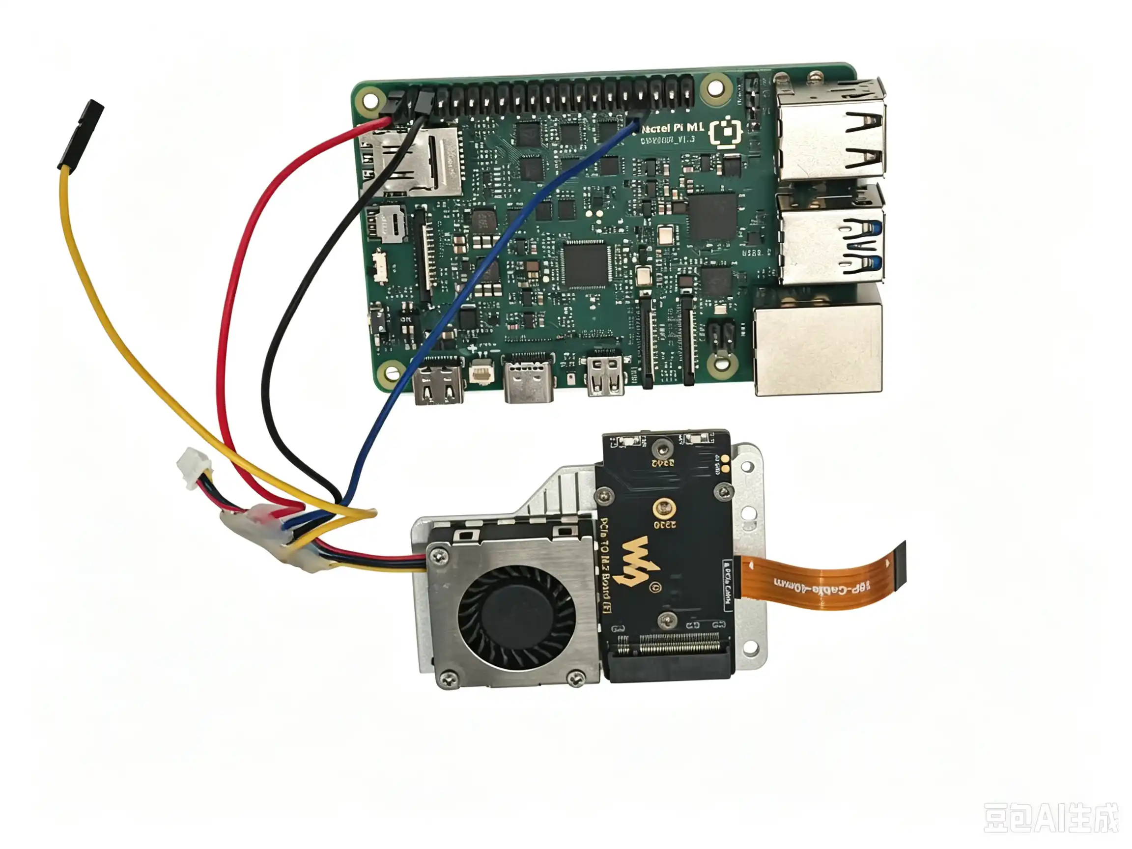
Temperature-controlled Fan Principle
The background process detects /sys/class/thermal/thermal_zone*
It reads the temperatures of several cores in turn, takes the highest value, and configures the PWM duty cycle of the fan according to the highest temperature.
Temperature |
Duty Cycle/255 |
|---|---|
<30℃ |
0 |
30~40℃ |
64 |
40~50℃ |
128 |
50~60℃ |
192 |
>60℃ |
255 |
Fan Pin |
M1 Development Board Pin (40PIN) |
|---|---|
Red wire (power positive) |
PIN2 |
Black wire (power negative) |
PIN5 |
Blue wire (PWM) |
PIN33 |
Test Process
The fan function is disabled by default. After booting, enter the corresponding command to check the status of the fan service.
/system/bin/sh /vendor/bin/40Pin-ctrl fan status #Check the current status of the fan service. If the fan service is not enabled, it shows disabled; if enabled, it shows enable
/system/bin/sh /vendor/bin/40Pin-ctrl fan enable #Enable the fan service. After enabling, you can check whether the status is enable
/system/bin/sh /vendor/bin/40Pin-ctrl fan disable #Disable the fan service. You only need to enter this command when stopping the test
Enter the following commands in the first terminal:
/system/bin/sh /vendor/bin/40Pin-ctrl fan status
/system/bin/sh /vendor/bin/40Pin-ctrl fan enable
#SC200U
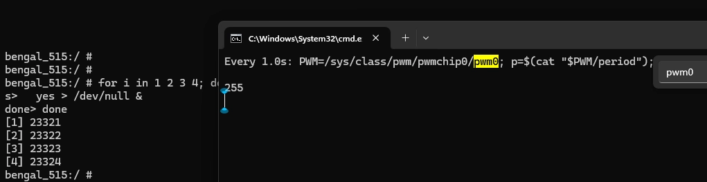
watch -n 1 'PWM=/sys/class/pwm/pwmchip0/pwm0; p=$(cat "$PWM/period"); d=$(cat "$PWM/duty_cycle"); echo $(( (d * 255 + p / 2) / p ))'
#SC200E
watch -n 1 'PWM=/sys/bus/platform/devices/1c40000.qcom,spmi:qcom,pm2250@1:qcom,pwms@be00/pwm/pwmchip2/pwm0; p=$(cat "$PWM/period"); d=$(cat "$PWM/duty_cycle"); echo $(( (d * 255 + p / 2) / p ))'
Open a second terminal to increase the temperature:
for i in 1 2 3 4; do
  yes > /dev/null &
done
If the temperature increase in step 3 is not sufficient, you can increase the load:
for i in $(seq 1 $(nproc)); do
  yes > /dev/null &
done
Check whether the temperature and the PWM duty cycle of the fan in the two terminals match the values in the table.
Stop the load after the test is completed:
killall yes
Application Scenarios
Media Entertainment Terminal: Using the Quectel Pi M1 intelligent main control board as a media entertainment terminal, you can play videos, music, view pictures, etc.
Industrial Data Visualization Platform: Using the Quectel Pi M1 intelligent main control board as an industrial data visualization platform, you can display industrial data, monitor equipment operation, perform data processing, etc.
Intelligent Interactive Terminal: Using the Quectel Pi M1 intelligent main control board as an intelligent interactive terminal, it can be applied to various human-computer interaction applications.
Troubleshooting
How to View System Logs
To view system logs, you need to connect the serial cable to the computer and use a serial port tool to view the logs.
Black Screen Issue
After the device is connected normally, if the screen displays black after booting, it may be caused by the following situations:
Power Connection Problem:
Check whether the power supply interface of the display screen is correctly connected, confirm that at least one of the 4 power supply interfaces is correctly connected, ensure that the power supply screws are tightened, and the thimble is in good contact with the 40-pin interface.
Connection Line Problem:
Check whether the MIPI flat cable is correctly inserted and firmly connected, confirm whether the direction of the flat cable is correct to avoid reverse insertion, and check whether the connector has physical damage.
System Startup Problem:
Confirm that the system has started normally and loaded the display service, and check the system logs to confirm whether the display driver is loaded normally.
Screen Distortion Issue
After the device is connected normally, if the screen displays distorted images after booting, it may be caused by the following situations:
Signal Interference:
Check whether the MIPI flat cable is too long or of poor quality, confirm whether there are strong electromagnetic interference sources around the flat cable, and try to replace it with a high-quality MIPI flat cable.
Hardware Compatibility Problem:
Confirm that the display model used is fully compatible with the Quectel Pi M1, and check whether the display firmware version is the latest.
Abnormal Touch Function
Abnormal touch function may be caused by the following situations:
Driver Problem:
Confirm that the system has correctly loaded the touch screen driver, and check whether the I2C communication is established normally.