40-Pin Expansion Header
The Quectel Pi M1/L1 intelligent main control board provides a standard 40‑pin GPIO expansion header, which supports multiple peripheral interfaces including GPIO, I2C, SPI, UART, and PWM. The following section describes how to test the functionality of these interfaces.
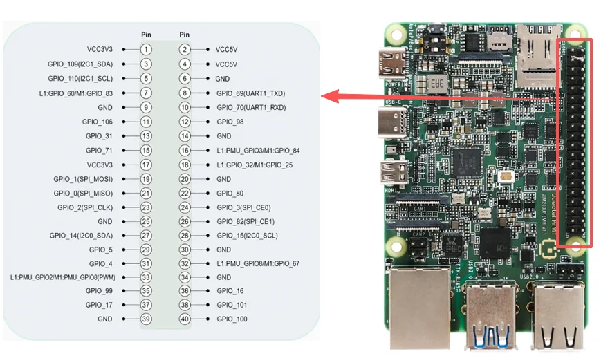
Pin Definition
Function3 |
Function2 |
Function1 |
L1 GPIO# |
M1 GPIO# |
Pin# |
Pin# |
M1 GPIO# |
L1 GPIO# |
Function1 |
Function2 |
Function3 |
|---|---|---|---|---|---|---|---|---|---|---|---|
VCC 3V3 |
1 |
2 |
VCC 5V |
||||||||
Common IIC SDA |
GPIO_109(I2C1_SDA) |
3 |
4 |
VCC 5V |
|||||||
Common IIC SCL |
GPIO_110(I2C1_SCL) |
5 |
6 |
GND |
|||||||
GPIO_60 |
GPIO_83 |
7 |
8 |
GPIO_69(UART1_TXD) |
SPI1_SCLK |
UART1_TX |
|||||
GND |
9 |
10 |
GPIO_70(UART1_RXD) |
SPI1_CS_N |
UART1_RX |
||||||
GPIO_106 |
11 |
12 |
GPIO_98 |
||||||||
GPIO_31 |
13 |
14 |
GND |
||||||||
UART2_TX |
SPI2_SCLK |
GPIO_71 |
15 |
16 |
GPIO_84 |
PMU_GPIO3 |
|||||
VCC 3V3 |
17 |
18 |
GPIO_25 |
GPIO_32 |
|||||||
I2C0_SCL |
UART0_RTS |
SPI0_MOSI |
GPIO_1(SPI_MOSI) |
19 |
20 |
GND |
|||||
I2C0_SDA |
UART0_CTS |
SPI0_MISO |
GPIO_0(SPI_MISO) |
21 |
22 |
GPIO_80 |
SPI2_CS_N |
UART2_RX |
|||
UART0_TX |
SPI0_SCLK |
GPIO_2(SPI_CLK) |
23 |
24 |
GPIO_3(SPI_CE0) |
SPI0_CS_N_0 |
UART0_RX |
||||
GND |
25 |
26 |
GPIO_82(SPI_CE1) |
||||||||
I2C5_SDA |
UART5_CTS |
SPI5_MISO |
GPIO_14(I2C0_SDA) |
27 |
28 |
GPIO_15(I2C0_SCL) |
SPI5_MOSI |
UART5_RTS |
I2C5_SCL |
||
I2C1_SCL |
UART1_RTS |
SPI1_MOSI |
GPIO_5 |
29 |
30 |
GND |
|||||
I2C1_SDA |
UART1_CTS |
SPI1_MISO |
GPIO_4 |
31 |
32 |
GPIO_67 |
PMU_GPIO8 |
||||
PWM |
PMU_GPIO2(PWM) |
PMU_GPIO8(PWM) |
33 |
34 |
GND |
||||||
GPIO_99 |
35 |
36 |
GPIO_16 |
SPI5_SCLK |
UART5_TX |
||||||
UART5_RX |
SPI5_CS_N |
GPIO_17 |
37 |
38 |
GPIO_101 |
||||||
GND |
39 |
40 |
GPIO_100 |
||||||||
GPIO Test
Hardware Connection
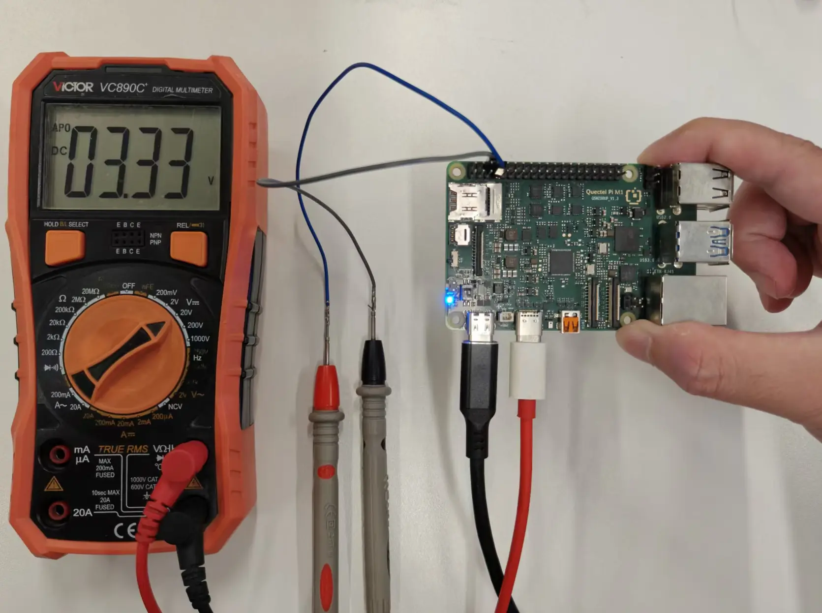
Take Pin13 (GPIO_31) as an example: connect the positive probe of the multimeter to Pin13, and the negative probe to GND (such as Pin14). When testing other GPIOs, simply change the line offset in the command to the corresponding GPIO number.
Test Method
After entering adb shell, use the gpiod command to test GPIO. For regular SoC GPIOs, use gpiochip0, and GPIO_31 corresponds to line 31 of gpiochip0.
adb shell

# View the GPIO controller
gpiodetect

# Check the status of the specified GPIO
gpioinfo gpiochip0 | grep -E "line[[:space:]]+31:"

# Read the current GPIO level
gpioget gpiochip0 31

# Pull the GPIO high and hold for 10 seconds.
gpioset --mode=time --sec=10 gpiochip0 31=1

# Pull the GPIO low and hold for 10 seconds.
gpioset --mode=time --sec=10 gpiochip0 31=0
GPIO interrupt test method: Connect the GPIO under test to a key or an external signal source to make the pin level change; use gpiomon to monitor the rising edge and falling edge events of this GPIO. Here, GPIO_31 is still taken as an example.
# Check the current level of GPIO_31
gpioget gpiochip0 31

# Monitor the rising edge and falling edge events of GPIO_31, and exit after being triggered 5 times.
gpiomon --num-events=5 --rising-edge --falling-edge gpiochip0 31
Note: If an error occurs gpiodetect: error while loading shared libraries: libgpiod.so.2: cannot open shared object file: No such file or directory,Execute first export LD_LIBRARY_PATH=/opt/qcom/lib:$LD_LIBRARY_PATH and then run the gpiod command.
Multimeter Measurement Results: If the measured voltage is close to 3.3V when a high-level output is executed, and close to 0V when a low-level output is executed, the GPIO output function can be determined to be normal.
I2C Test
Pins 3 and 5 on the 40‑pin header are by default the I2C data and clock pins. To test the I2C interface, we need to connect an external I2C device. Here we use the Waveshare environmental sensor expansion board, and its corresponding device node is /dev/i2c-1.
Test Preparation
|
|
|
|
|---|---|---|---|
WSL25911FN |
0x29 |
0x12 |
0x50 |
BME280 |
0x76 |
0xD0 |
0x60 |
MPU9250 |
0x68 |
0x75 |
0x71 |
LTR390-UV-1 |
0x53 |
0x06 |
0xB2 |
PS: For the WSL25911FN used here, the command bit (0xA0) needs to be included when reading the ID register. That is, when accessing register 0x12, it is actually written as 0xA0 | 0x12 = 0xB2; no other registers require this.
This test uses the Waveshare environmental sensor expansion board, which is connected via the 40‑pin header.
Hardware Connection Diagram:
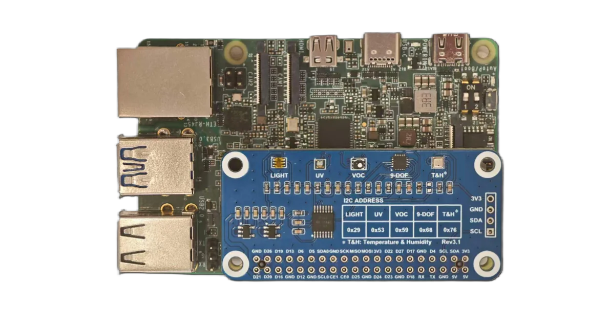
Quectel Pi M1 connected to the expansion board
Test Procedure
adb shell # Enter the ADB shell
ls -al /dev/i2c* # Check whether I2C-1 exists in the corresponding directory
i2cdetect -y 1   # Check how many devices are attached to the corresponding I2C bus
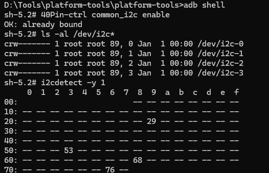
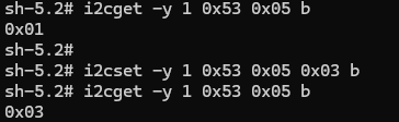
I2C Read/Write
i2cget -y 1 0x53 0x05 b # Read the value of register 0x05 at device address 0x53 on i2c‑1, size one byte
i2cset -y 1 0x53 0x05 0x03 b # Set the value of register 0x05 at device address 0x53 on i2c‑1 to 0x03, size one byte
SPI Test
Here we use the 2.23-inch OLED expansion board.
The device chip-select nodes for the SPI function on the 40‑pin header are /dev/spidev0.0 and /dev/spidev0.1. To view these nodes, enter the following in adb:
adb shell # Enter the ADB shell
ls /dev/spidev* # View SPI devices
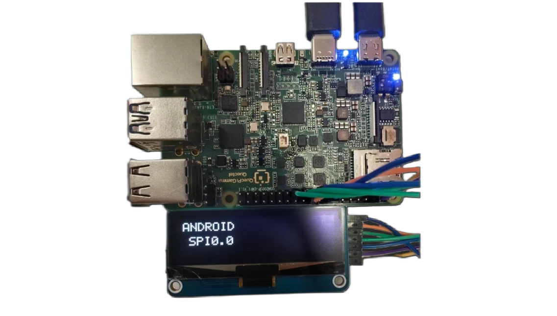
Waveshare OLED display test (CS0 and CS1)
Please connect the wiring according to the following table:
OLED Pin |
Connect To |
SC200U Physical Pin |
Remarks |
|---|---|---|---|
VCC |
3.3V power |
Pin1 or Pin17 |
Must be 3.3V |
GND |
Ground |
Any GND pin (e.g., Pin6, Pin9, Pin14) |
Common ground |
DIN/MOSI |
SPI data |
Pin19 |
SPI_MOSI |
CLK/SCK |
SPI clock |
Pin23 |
SPI_CLK |
CS/CE |
Chip select |
Pin24/Pin26 |
SPI_CE0/SPI_CE1 |
D/C |
Data/Command |
Pin22 |
GPIO80 |
RES/RST |
Reset |
Pin18 |
M1: GPIO25 |
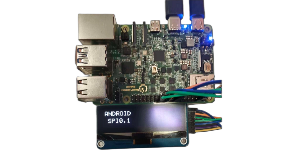
Hardware Connection Diagram:
On the Linux host, create the SPI test file spi_oled_demo.c:
 #include <stdio.h>
 #include <stdlib.h>
 #include <stdint.h>
 #include <string.h>
 #include <unistd.h>
 #include <fcntl.h>
 #include <sys/ioctl.h>
 #include <linux/spi/spidev.h>
 #include <time.h>

#define GPIO_BASE   385
#define GPIO_RST    (GPIO_BASE + 32)
#define GPIO_DC     (GPIO_BASE + 80)
// 大多数 SSD1306/SH1106 SPI OLED 使用 MODE0,先改为 MODE0,降速到 4MHz 提高可靠性
#define SPI_MODE    SPI_MODE_0
#define SPI_SPEED   4000000

 #define OLED_WIDTH  128
 #define OLED_HEIGHT 32
 #define OLED_PAGES  4

 // Complete 5x7 font
 static const uint8_t font_5x7[][5] = {
     {0x00, 0x00, 0x00, 0x00, 0x00}, // Space
     {0x3E, 0x51, 0x49, 0x45, 0x3E}, // 0
     {0x00, 0x42, 0x7F, 0x40, 0x00}, // 1
     {0x42, 0x61, 0x51, 0x49, 0x46}, // 2
     {0x21, 0x41, 0x45, 0x4B, 0x31}, // 3
     {0x18, 0x14, 0x12, 0x7F, 0x10}, // 4
     {0x27, 0x45, 0x45, 0x45, 0x39}, // 5
     {0x3C, 0x4A, 0x49, 0x49, 0x30}, // 6
     {0x01, 0x71, 0x09, 0x05, 0x03}, // 7
     {0x36, 0x49, 0x49, 0x49, 0x36}, // 8
     {0x06, 0x49, 0x49, 0x29, 0x1E}, // 9
     {0x7E, 0x11, 0x11, 0x11, 0x7E}, // A
     {0x7F, 0x49, 0x49, 0x49, 0x36}, {0x3E, 0x41, 0x41, 0x41, 0x22}, // B C
     {0x7F, 0x41, 0x41, 0x22, 0x1C}, {0x7F, 0x49, 0x49, 0x49, 0x41}, // D E
     {0x7F, 0x09, 0x09, 0x09, 0x01}, {0x3E, 0x41, 0x49, 0x49, 0x7A}, // F G
     {0x7F, 0x08, 0x08, 0x08, 0x7F}, {0x00, 0x41, 0x7F, 0x41, 0x00}, // H I
     {0x20, 0x40, 0x41, 0x3F, 0x01}, {0x7F, 0x08, 0x14, 0x22, 0x41}, // J K
     {0x7F, 0x40, 0x40, 0x40, 0x40}, {0x7F, 0x02, 0x0C, 0x02, 0x7F}, // L M
     {0x7F, 0x04, 0x08, 0x10, 0x7F}, {0x3E, 0x41, 0x41, 0x41, 0x3E}, // N O
     {0x7F, 0x09, 0x09, 0x09, 0x06}, {0x3E, 0x41, 0x51, 0x21, 0x5E}, // P Q
     {0x7F, 0x09, 0x19, 0x29, 0x46}, {0x46, 0x49, 0x49, 0x49, 0x31}, // R S
     {0x01, 0x01, 0x7F, 0x01, 0x01}, {0x3F, 0x40, 0x40, 0x40, 0x3F}, // T U
     {0x1F, 0x20, 0x40, 0x20, 0x1F}, {0x3F, 0x40, 0x38, 0x40, 0x3F}, // V W
     {0x63, 0x14, 0x08, 0x14, 0x63}, {0x07, 0x08, 0x70, 0x08, 0x07}, // X Y
     {0x61, 0x51, 0x49, 0x45, 0x43}, // Z
     {0x08, 0x08, 0x08, 0x08, 0x08}, // -
     {0x00, 0x36, 0x36, 0x00, 0x00}, // :
     {0x00, 0x60, 0x60, 0x00, 0x00}, // .
 };

 static int char_to_index(char c) {
     if (c == ' ') return 0;
     if (c >= '0' && c <= '9') return 1 + (c - '0');
     if (c >= 'A' && c <= 'Z') return 11 + (c - 'A');
     if (c >= 'a' && c <= 'z') return 11 + (c - 'a');
     if (c == '-') return 37;
     if (c == ':') return 38;
     if (c == '.') return 39;
     return 0;
 }

 int gpio_write(int gpio, int value);
 void oled_quick_test(const char *device, const char *name);

  int main() {
     printf("\n╔════════════════════════════════════════════════════════╗\n");
     printf("║  Chip Select Pin Comparison Tool                      ║\n");
     printf("╚════════════════════════════════════════════════════════╝\n");

     printf("\nThis tool helps identify which CS pin is connected.\n");
     printf("\nInstruction:\n");
     printf("  1. Connect OLED CS to Pin24 first\n");
     printf("  2. Run test - should see display\n");
     printf("  3. Move OLED CS to Pin26\n");
     printf("  4. Run test again - should see display\n");
     printf("\n");
     char choice;
     printf("Which pin is your OLED CS currently connected to?\n");
     printf("  [0] Pin24 (CE0)\n");
     printf("  [1] Pin26 (CE1)\n");
     printf("Choice: ");
     scanf(" %c", &choice);

     if (choice == '0') {
         printf("\nTesting CE0 (Pin24)...\n");
         oled_quick_test("/dev/spidev0.0", "CE0-PIN24");
     } else if (choice == '1') {
         printf("\nTesting CE1 (Pin26)...\n");
         oled_quick_test("/dev/spidev0.1", "CE1-PIN26");
     } else {
         printf("Invalid choice\n");
         return 1;
     }

     return 0;
 }

 void oled_quick_test(const char *device, const char *name) {
     // Display buffer
     static uint8_t buffer[OLED_PAGES][OLED_WIDTH];

     // Simple GPIO functions
     int gpio_export(int gpio) {
         int fd = open("/sys/class/gpio/export", O_WRONLY);
         if (fd < 0) return -1;
         char buf[10];
         snprintf(buf, sizeof(buf), "%d", gpio);
         write(fd, buf, strlen(buf));
         close(fd);
         usleep(100000);
         return 0;
     }

      int gpio_set_dir(int gpio) {
         char path[50];
         snprintf(path, sizeof(path), "/sys/class/gpio/gpio%d/direction", gpio);
         int fd = open(path, O_WRONLY);
         if (fd < 0) return -1;
         write(fd, "out", 3);
         close(fd);
         return 0;
     }

     int gpio_write(int gpio, int value) {
         char path[50];
         snprintf(path, sizeof(path), "/sys/class/gpio/gpio%d/value", gpio);
         int fd = open(path, O_WRONLY);
         if (fd < 0) return -1;
         char buf[2] = {value ? '1' : '0', 0};
         write(fd, buf, 1);
         close(fd);
         return 0;
     }

     int configure_spi(int fd) {
         uint8_t mode = SPI_MODE;
         uint32_t speed = SPI_SPEED;

         if (ioctl(fd, SPI_IOC_WR_MODE, &mode) < 0) {
             perror("  ERROR: Cannot set SPI mode");
             return -1;
         }
         if (ioctl(fd, SPI_IOC_WR_MAX_SPEED_HZ, &speed) < 0) {
             perror("  ERROR: Cannot set SPI speed");
             return -1;
         }

         printf("  SPI configured: mode %u, speed %u Hz\n", mode, speed);
         return 0;
     }

     void send_cmd(int fd, uint8_t cmd) {
         gpio_write(GPIO_DC, 0);
         write(fd, &cmd, 1);
         usleep(1000);
     }

      void set_pixel(int x, int y, int color) {
         if (x >= 0 && x < OLED_WIDTH && y >= 0 && y < OLED_HEIGHT) {
             int page = y / 8;
             int bit = y % 8;
             if (color)
                 buffer[page][x] |= (1 << bit);
             else
                 buffer[page][x] &= ~(1 << bit);
         }
     }

     void draw_char(int x, int y, char c) {
         int idx = char_to_index(c);
         for (int col = 0; col < 5; col++) {
             uint8_t data = font_5x7[idx][col];
             for (int row = 0; row < 8; row++) {
                 if (data & (1 << row)) {
                     set_pixel(x + col, y + row, 1);
                 }
             }
         }
     }

     void draw_text(int x, int y, const char *text) {
         int cursor = x;
         while (*text) {
             draw_char(cursor, y, *text);
             cursor += 6;
             text++;
         }
     }

     void clear_buffer() {
         memset(buffer, 0, OLED_PAGES * OLED_WIDTH);
     }

     void display_buffer(int fd) {
         for (int page = 0; page < OLED_PAGES; page++) {
             send_cmd(fd, 0xB0 + page);
             send_cmd(fd, 0x04);
             send_cmd(fd, 0x10);
             gpio_write(GPIO_DC, 1);
             write(fd, buffer[page], OLED_WIDTH);
         }
     }

     // Initialize GPIO
     gpio_export(GPIO_RST);
     gpio_export(GPIO_DC);
     usleep(200000);
     gpio_set_dir(GPIO_RST);
     gpio_set_dir(GPIO_DC);

     // Open SPI
     printf("  Opening %s...\n", device);
     int spi_fd = open(device, O_RDWR);
     if (spi_fd < 0) {
         perror("  ERROR: Cannot open device");
         printf("  → %s is NOT working or OLED not connected\n", name);
         return;
     }
     printf("  ✓ Device opened\n");

     // Configure SPI
     if (configure_spi(spi_fd) < 0) {
         printf("  → %s SPI configuration failed\n", name);
         close(spi_fd);
         return;
     }

     // Reset OLED
     printf("  Resetting OLED...\n");
     gpio_write(GPIO_RST, 0);
     usleep(50000);
     gpio_write(GPIO_RST, 1);
     usleep(50000);

     // Initialize OLED
     printf("  Initializing OLED...\n");
     send_cmd(spi_fd, 0xAE);
     send_cmd(spi_fd, 0x04); send_cmd(spi_fd, 0x10); send_cmd(spi_fd, 0x40);
     send_cmd(spi_fd, 0x81); send_cmd(spi_fd, 0xFF);
     send_cmd(spi_fd, 0xA1); send_cmd(spi_fd, 0xA6);
     send_cmd(spi_fd, 0xA8); send_cmd(spi_fd, 0x1F);
     send_cmd(spi_fd, 0xC8);
     send_cmd(spi_fd, 0xD3); send_cmd(spi_fd, 0x00);
     send_cmd(spi_fd, 0xD5); send_cmd(spi_fd, 0xF0);
     send_cmd(spi_fd, 0xD8); send_cmd(spi_fd, 0x05);
     send_cmd(spi_fd, 0xD9); send_cmd(spi_fd, 0xC2);
     send_cmd(spi_fd, 0xDA); send_cmd(spi_fd, 0x12);
     send_cmd(spi_fd, 0xDB); send_cmd(spi_fd, 0x08);
     send_cmd(spi_fd, 0xAF);
     printf("  ✓ OLED initialized\n");

     // Test 1: Display "USING: CE0" or "USING: CE1"
     printf("\n  [Test 1] Displaying chip select info...\n");
     clear_buffer();
     draw_text(10, 4, "USING:");
     if (strstr(name, "CE0")) {
         draw_text(25, 16, "CE0");
     } else {
         draw_text(25, 16, "CE1");
     }
     display_buffer(spi_fd);
     printf("  ✓ Screen showing: USING %s\n", strstr(name, "CE0") ? "CE0" : "CE1");
     sleep(3);

     // Test 2: Fill white
     printf("\n  [Test 2] Filling screen WHITE...\n");
     memset(buffer, 0xFF, OLED_PAGES * OLED_WIDTH);
     display_buffer(spi_fd);
     printf("  ✓ Screen should be WHITE\n");
     sleep(2);

     // Test 3: Blink test
     printf("\n  [Test 3] Blink test (5 times)...\n");
     for (int i = 0; i < 5; i++) {
         // White
         memset(buffer, 0xFF, OLED_PAGES * OLED_WIDTH);
         display_buffer(spi_fd);
         usleep(200000);

         // Black
         memset(buffer, 0x00, OLED_PAGES * OLED_WIDTH);
         display_buffer(spi_fd);
         usleep(200000);

         printf("    Blink %d/5\n", i + 1);
     }
     printf("  ✓ Blink test complete\n");

     // Test 4: FPS Performance Test
     printf("\n  [Test 4] FPS Performance Test...\n");
     printf("  Running 100 frame updates...\n");

     struct timespec start, end;
     clock_gettime(CLOCK_MONOTONIC, &start);

     for (int frame = 0; frame < 100; frame++) {
         // Generate test pattern
         for (int page = 0; page < OLED_PAGES; page++) {
             for (int x = 0; x < OLED_WIDTH; x++) {
                 buffer[page][x] = (x + frame) & 0xFF;
             }
         }
         display_buffer(spi_fd);
     }

     clock_gettime(CLOCK_MONOTONIC, &end);
     double elapsed = (end.tv_sec - start.tv_sec) +
                      (end.tv_nsec - start.tv_nsec) / 1000000000.0;
     double fps = 100.0 / elapsed;

     printf("  ✓ Performance: %.1f FPS\n", fps);

     // Display FPS result on screen
     clear_buffer();
     draw_text(10, 4, "FPS TEST");
     char fps_str[20];
     snprintf(fps_str, sizeof(fps_str), "%.1f FPS", fps);
     draw_text(20, 16, fps_str);
     display_buffer(spi_fd);
     printf("  ✓ FPS result displayed on screen\n");
     sleep(3);

     // Test 5: CS Pin Functionality Test
     printf("\n  [Test 5] CS Pin Functionality Test...\n");
     printf("  This test verifies CS pin actually controls the device\n");

     // Step 1: Display number 1
     printf("  Step 1: Displaying pattern 1...\n");
     clear_buffer();
     draw_text(15, 4, "PATTERN");
     draw_text(50, 16, "1");
     display_buffer(spi_fd);
     sleep(2);

     // Step 2: Try to update through the OTHER CS (should fail if CS works)
     printf("  Step 2: Trying to update via OTHER CS...\n");
     const char *other_device = strstr(name, "CE0") ? "/dev/spidev0.1" : "/dev/spidev0.0";
     const char *other_name = strstr(name, "CE0") ? "CE1" : "CE0";

     int other_fd = open(other_device, O_RDWR);
     if (other_fd >= 0) {
         if (configure_spi(other_fd) < 0) {
             close(other_fd);
             printf("  Skipping %s update because SPI configuration failed\n", other_name);
             goto update_back;
         }

         // Try to display pattern 2 via other CS
         clear_buffer();
         draw_text(15, 4, "PATTERN");
         draw_text(50, 16, "2");

         for (int page = 0; page < OLED_PAGES; page++) {
             send_cmd(other_fd, 0xB0 + page);
             send_cmd(other_fd, 0x04);
             send_cmd(other_fd, 0x10);
             gpio_write(GPIO_DC, 1);
             write(other_fd, buffer[page], OLED_WIDTH);
         }

         close(other_fd);
         printf("  Sent update via %s (other CS)\n", other_name);
         sleep(2);

         printf("\n  ╔════════════════════════════════════════════════╗\n");
         printf("  ║ CHECK SCREEN: Still showing '1' or changed to '2'? ║\n");
         printf("  ╚════════════════════════════════════════════════╝\n");
         printf("\n  If still showing '1': CS pin is WORKING correctly ✓\n");
         printf("  If changed to '2': CS pin NOT working (both CS active) ✗\n\n");
         sleep(2);
     }

     // Step 3: Update back via correct CS
update_back:
     printf("  Step 3: Updating via correct CS (%s)...\n", name);
     clear_buffer();
     draw_text(15, 4, "BACK TO");
     draw_text(50, 16, "1");
     display_buffer(spi_fd);
     printf("  ✓ Should see pattern 1 again\n");
     sleep(2);

     // Test 6: FPS result summary
     printf("\n  [Test 6] Final Summary...\n");
     clear_buffer();
     draw_text(30, 4, name);
     char summary_str[20];
     snprintf(summary_str, sizeof(summary_str), "%.1fFPS", fps);
     draw_text(20, 16, summary_str);
     display_buffer(spi_fd);
     printf("  ✓ Summary displayed\n");
     sleep(3);

     // Clear screen
     clear_buffer();
     display_buffer(spi_fd);

     close(spi_fd);

     printf("\n======================================================================\n");
     printf("  %s Test Complete!\n", name);
     printf("======================================================================\n");
     printf("  CS Pin Test Result:\n");
     printf("    If screen didn't change to '2' in Step 2:\n");
     printf("      → CS pin is working correctly ✓\n");
     printf("    If screen changed to '2':\n");
     printf("      → CS pin might not be controlling the device ✗\n");
     printf("      → Both CS pins may be active simultaneously\n");
     printf("\n  Performance: %.1f FPS\n", fps);
     printf("======================================================================\n");
 }
After the file is created, compile it into an executable:
mkdir -p out # Create the output directory
aarch64-linux-gnu-gcc spi_oled_demo.c -O2 -Wall -Wextra -o spi_oled_demo # Compile into an executable
Copy the compiled file from the Linux environment to the same directory as the ADB shell.
Execution steps:
adb push spi_oled_demo /tmp/spi_oled_demo
adb shell chmod +x /tmp/spi_oled_demo
adb shell
/tmp/spi_oled_demo
After the program runs, it will prompt you to select the SPI device:
Select 0: use
/dev/spidev0.0(CE0, Pin24)Select 1: use
/dev/spidev0.1(CE1, Pin26)
Please select the corresponding device according to your actual wiring (if the CS/CE pin is connected to pin24, select 0; if connected to pin26, select 1).
Test results:
After execution, the program will perform the following tests in sequence:
╔══════════════════════════════════════════════════════╗
║        Android SPI OLED Test Program                ║
║        For Android Devices                          ║
╚══════════════════════════════════════════════════════╝

Select SPI device:
  [0] /dev/spidev0.0 (CE0, Pin24)
  [1] /dev/spidev0.1 (CE1, Pin26)
  [c] Custom device path
Selection: 1

Using device: /dev/spidev0.1

Initializing GPIO...
  ✓ GPIO initialization successful

Opening SPI device: /dev/spidev0.1
  ✓ SPI device opened and configured
    - Mode: 3
    - Speed: 2000000 Hz
    - Bits per word: 8 bits

Initializing OLED...
  Resetting OLED...
  Sending initialization commands...
  ✓ OLED initialization complete

━━━━━━━━━━━━━━━━━━━━━━━━━━━━━━━━━━━━━━━━━━━━━━
  Starting test sequence: SPI0.1
━━━━━━━━━━━━━━━━━━━━━━━━━━━━━━━━━━━━━━━━━━━━━━

[Test 1] Display device info...
  ✓ Screen should display: ANDROID SPI0.1

[Test 2] Full white screen test...
  ✓ Screen should be fully white

[Test 3] Blink test (5 times)...
    Blink 1/5
    Blink 2/5
    Blink 3/5
    Blink 4/5
    Blink 5/5
  ✓ Blink test complete

[Test 4] FPS performance test...
  Running 100 frame updates...
  ✓ Performance: 40.3 FPS (elapsed: 2.48 seconds)
  ✓ FPS result displayed

[Test 5] Pattern test...
  Pattern 1: Horizontal stripes
  Pattern 2: Vertical stripes
  Pattern 3: Checkerboard
  ✓ Pattern test complete

[Test 6] Test summary...
  ✓ Summary displayed
Test Descriptions:
Test 1: Verifies that the OLED can display text information normally.
Test 2: Verifies the OLED full‑screen display function.
Test 3: Verifies the OLED refresh function through the blinking test.
Test 4: Tests SPI communication performance (FPS value).
Test 5: Tests the display of different patterns.
Test 6: Displays the test summary information.
If all test items show a ✓ mark, it indicates that both SPI communication and the OLED function are working properly.
UART Test
On the 40‑pin header, pin8 and 10 are configured by default as UART functions, with the corresponding device node being /dev/ttyHS0.
Viewing Serial Devices
You can use the following command to view all serial devices in the system:
ls /dev/tty*
UART Loopback Test
This test verifies whether the UART transmit and receive functions are working properly by shorting pins 8 and 10 together.
Hardware Connection: Short pin 8 (TX) and pin 10 (RX) on the 40‑pin header.
Create the UART test file on the Linux host:
Create a new file named uart_loopback.c with the following content:
#include <stdio.h>
#include <stdlib.h>
#include <string.h>
#include <unistd.h>
#include <fcntl.h>
#include <termios.h>
#include <errno.h>
#include <signal.h>

static int serial_fd = -1;
static volatile int running = 1;

void signal_handler(int sig) {
    printf("\n用户中断测试\n");
    running = 0;
    if (serial_fd >= 0) {
        close(serial_fd);
        printf("串口已关闭\n");
    }
    exit(0);
}

int configure_serial(int fd, int baudrate) {
    struct termios tty;

    if (tcgetattr(fd, &tty) != 0) {
        printf("获取串口属性失败: %s\n", strerror(errno));
        return -1;
    }

    speed_t speed;
    switch (baudrate) {
        case 9600:   speed = B9600;   break;
        case 19200:  speed = B19200;  break;
        case 38400:  speed = B38400;  break;
        case 57600:  speed = B57600;  break;
        case 115200: speed = B115200; break;
        case 230400: speed = B230400; break;
        default:     speed = B115200; break;
    }

    cfsetospeed(&tty, speed);
    cfsetispeed(&tty, speed);

    tty.c_cflag &= ~PARENB;
    tty.c_cflag &= ~CSTOPB;
    tty.c_cflag &= ~CSIZE;
    tty.c_cflag |= CS8;
    tty.c_cflag &= ~CRTSCTS;
    tty.c_cflag |= CREAD | CLOCAL;

    tty.c_iflag &= ~(IXON | IXOFF | IXANY);
    tty.c_iflag &= ~(ICANON | ECHO | ECHOE | ISIG);

    tty.c_oflag &= ~OPOST;

    tty.c_lflag &= ~(ICANON | ECHO | ECHOE | ISIG);

    tty.c_cc[VTIME] = 10;
    tty.c_cc[VMIN] = 0;

    if (tcsetattr(fd, TCSANOW, &tty) != 0) {
        printf("设置串口属性失败: %s\n", strerror(errno));
        return -1;
    }

    return 0;
}

int serial_loopback_test(const char* port, int baudrate) {
    char test_data[] = "Hello, Serial Loopback!";
    char received_data[256];
    ssize_t bytes_written, bytes_read;

    serial_fd = open(port, O_RDWR | O_NOCTTY | O_SYNC);
    if (serial_fd < 0) {
        printf("无法打开串口 %s: %s\n", port, strerror(errno));
        return -1;
    }

    if (configure_serial(serial_fd, baudrate) != 0) {
        close(serial_fd);
        return -1;
    }

    printf("串口 %s 已打开,开始回环测试(按Ctrl+C退出)...\n", port);

    while (running) {
        tcflush(serial_fd, TCIOFLUSH);

        bytes_written = write(serial_fd, test_data, strlen(test_data));
        if (bytes_written < 0) {
            printf("发送数据失败: %s\n", strerror(errno));
            break;
        }
        printf("发送: %s\n", test_data);

        usleep(100000);

        bytes_read = read(serial_fd, received_data, sizeof(received_data) - 1);
        if (bytes_read < 0) {
            printf("读取数据失败: %s\n", strerror(errno));
            break;
        }

        received_data[bytes_read] = '\0';

        if (bytes_read == (ssize_t)strlen(test_data) &&
            strncmp(received_data, test_data, strlen(test_data)) == 0) {
            printf("接收: %s → 测试通过\n\n", received_data);
        } else {
            printf("接收异常: 发送[%zu] vs 接收[%zd] → 测试失败\n",
                   strlen(test_data), bytes_read);
            if (bytes_read > 0) {
                printf("接收内容: %s\n\n", received_data);
            } else {
                printf("未接收到数据\n\n");
            }
        }

        sleep(1);
    }

    close(serial_fd);
    printf("串口 %s 已关闭\n", port);
    return 0;
}

void print_usage(const char* prog) {
    printf("UART回环测试程序\n\n");
    printf("用法:\n");
    printf("  %s -n <HS编号> [-b 波特率]     指定ttyHS编号\n", prog);
    printf("  %s -d <设备路径> [-b 波特率]    指定完整设备路径\n", prog);
    printf("  %s                             默认使用 /dev/ttyHS5 @ 115200\n\n", prog);
    printf("示例:\n");
    printf("  %s -n 3                  使用 /dev/ttyHS3 @ 115200\n", prog);
    printf("  %s -n 5 -b 9600         使用 /dev/ttyHS5 @ 9600\n", prog);
    printf("  %s -d /dev/ttyUSB0      使用 /dev/ttyUSB0 @ 115200\n", prog);
}

int main(int argc, char* argv[]) {
    char port_buf[64];
    const char* port = "/dev/ttyHS5";
    int baudrate = 115200;
    int opt;

    while ((opt = getopt(argc, argv, "n:d:b:h")) != -1) {
        switch (opt) {
            case 'n':
                snprintf(port_buf, sizeof(port_buf), "/dev/ttyHS%s", optarg);
                port = port_buf;
                break;
            case 'd':
                port = optarg;
                break;
            case 'b':
                baudrate = atoi(optarg);
                break;
            case 'h':
            default:
                print_usage(argv[0]);
                return (opt == 'h') ? 0 : 1;
        }
    }

    signal(SIGINT, signal_handler);
    signal(SIGTERM, signal_handler);

    printf("UART回环测试程序\n");
    printf("使用串口: %s\n", port);
    printf("波特率: %d\n", baudrate);
    printf("=====================================\n");

    return serial_loopback_test(port, baudrate);
}
After the file is created, compile it into an executable:
mkdir -p out # Create the output directory
aarch64-linux-gnu-gcc uart_loopback.c -O2 -Wall -Wextra -o out/uart_loopback # Compile into an executable
Copy the compiled file from the Linux environment to the same directory as the ADB shell.
Execution steps:
adb push uart_loopback /tmp/uart_loopback
adb shell chmod +x /tmp/uart_loopback
adb shell
/tmp/uart_loopback /dev/ttyHS1
Test results:
When pins 8 and 10 are correctly shorted, the program will continuously send data and verify whether the received data matches.
Using serial port: /dev/ttyHS1
Baud rate: 115200
=====================================
Serial port /dev/ttyHS1 opened, starting loopback test (Press Ctrl+C to exit)...

Sent: Hello, Serial Loopback!
Received: Hello, Serial Loopback! → Test passed

Sent: Hello, Serial Loopback!
Received: Hello, Serial Loopback! → Test passed

Sent: Hello, Serial Loopback!
Received: Hello, Serial Loopback! → Test passed
Press Ctrl+C to exit the test program. The program will automatically close the serial port and exit.
Temperature‑Controlled Fan Test
A background process monitors /sys/class/thermal/thermal_zone*, periodically reads the temperatures of several CPU cores, and takes the highest value. Based on this highest temperature, it configures the fan’s PWM duty cycle.
|
|
|---|---|
<30℃ |
0 |
30~40℃ |
64 |
40~50℃ |
128 |
50~60℃ |
192 |
>60℃ |
255 |
Wiring Diagram
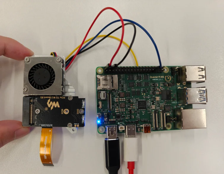
This test uses a Raspberry Pi fan. Connect it to the corresponding pins on the M1/L1 40‑pin header as shown in the diagram below.
Fan Pin |
M1 Development Board Pin (40‑PIN) |
|---|---|
Red wire (Power positive) |
PIN2 |
Black wire (Power negative) |
PIN6 |
Blue wire (PWM) |
PIN33 |
Yellow wire (Speed detection / tachometer) |
Not connected |
Test Procedure
By default, the fan function is disabled. After power‑on, enter the following commands in adb to check the status of the fan service.
adb shell
40pin-ctrl fan status # View the current status of the fan service (bound if not enabled, enable if active)
40pin-ctrl fan enable # Enable the fan service; after enabling, you can check whether the status shows "enable"
40pin-ctrl fan disable # Disable the fan service (only needed to stop the test)
Enter the following in the first terminal.
40pin-ctrl fan enable
40pin-ctrl fan status
#M1
watch -n 1 'PWM=/sys/bus/platform/devices/1c40000.qcom,spmi:qcom,pm6125@1:qcom,pwms@b300/pwm/pwmchip0/pwm0; p=$(cat "$PWM/period"); d=$(cat "$PWM/duty_cycle"); echo $(( (d * 255 + p / 2) / p ))'
#L1
watch -n 1 'PWM=/sys/bus/platform/devices/1c40000.qcom,spmi:qcom,pm2250@1:qcom,pwms@be00/pwm/pwmchip2/pwm0; p=$(cat "$PWM/period"); d=$(cat "$PWM/duty_cycle"); echo $(( (d * 255 + p / 2) / p ))'
Check whether the current temperature and PWM duty cycle match.
Open a second terminal and perform the heating (temperature‑raising) operation.
for i in 1 2 3 4; do
  yes > /dev/null &
done
If the temperature rise in step 3 is insufficient, you can increase the load.
for i in $(seq 1 $(nproc)); do
  yes > /dev/null &
done
Check whether the temperatures and fan PWM duty cycles in the two terminals match the values in the table.
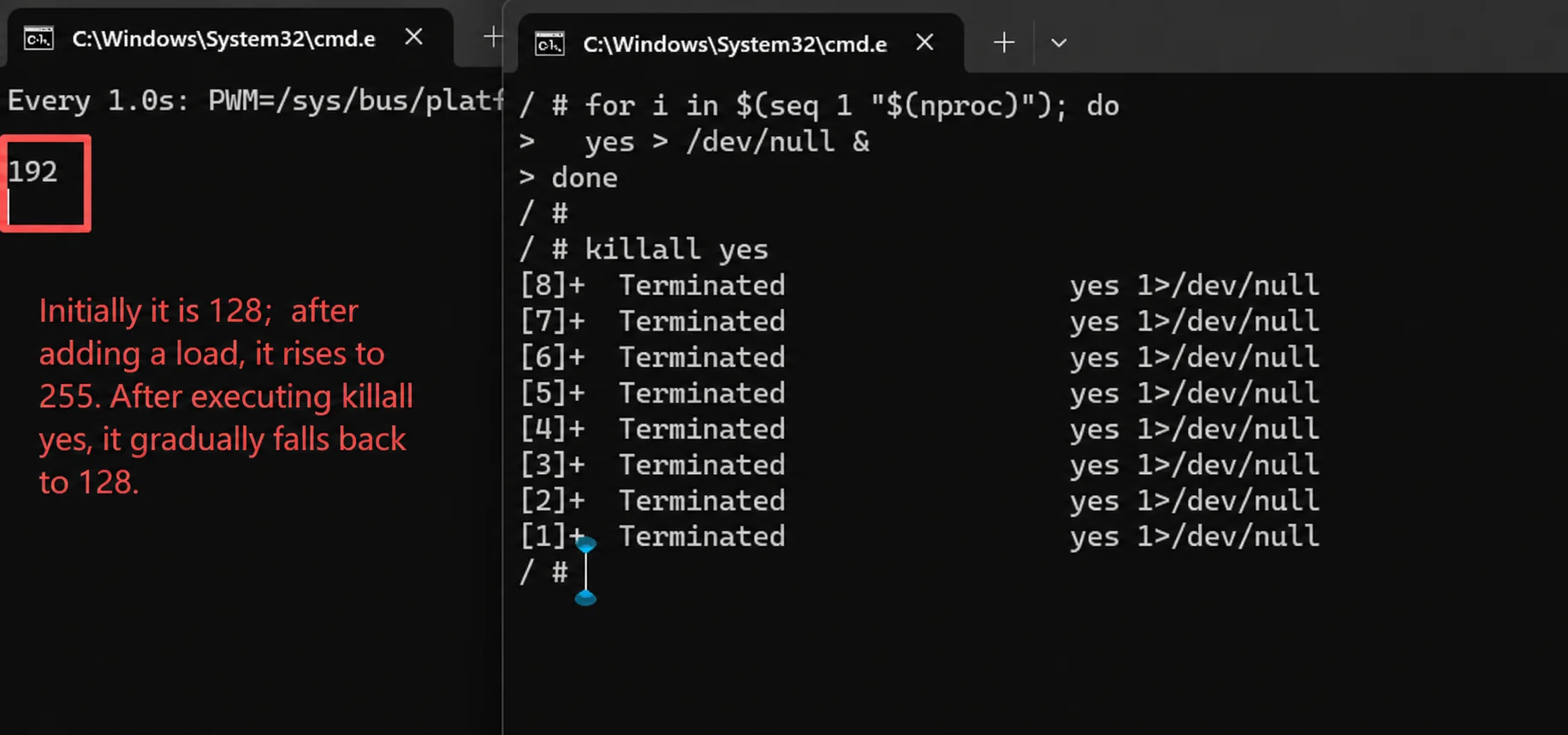
After the test ends, stop the load.
killall yes