40‑Pin扩展
Copyright © Quectel Wireless Solutions Co., Ltd. 2026. All rights reserved.
Quectel Pi M1/L1 智能主控板提供了标准的40‑pin GPIO扩展接口,支持GPIO、I2C、SPI、UART、PWM等多种外设接口,下面将介绍如何测试这些接口的功能。
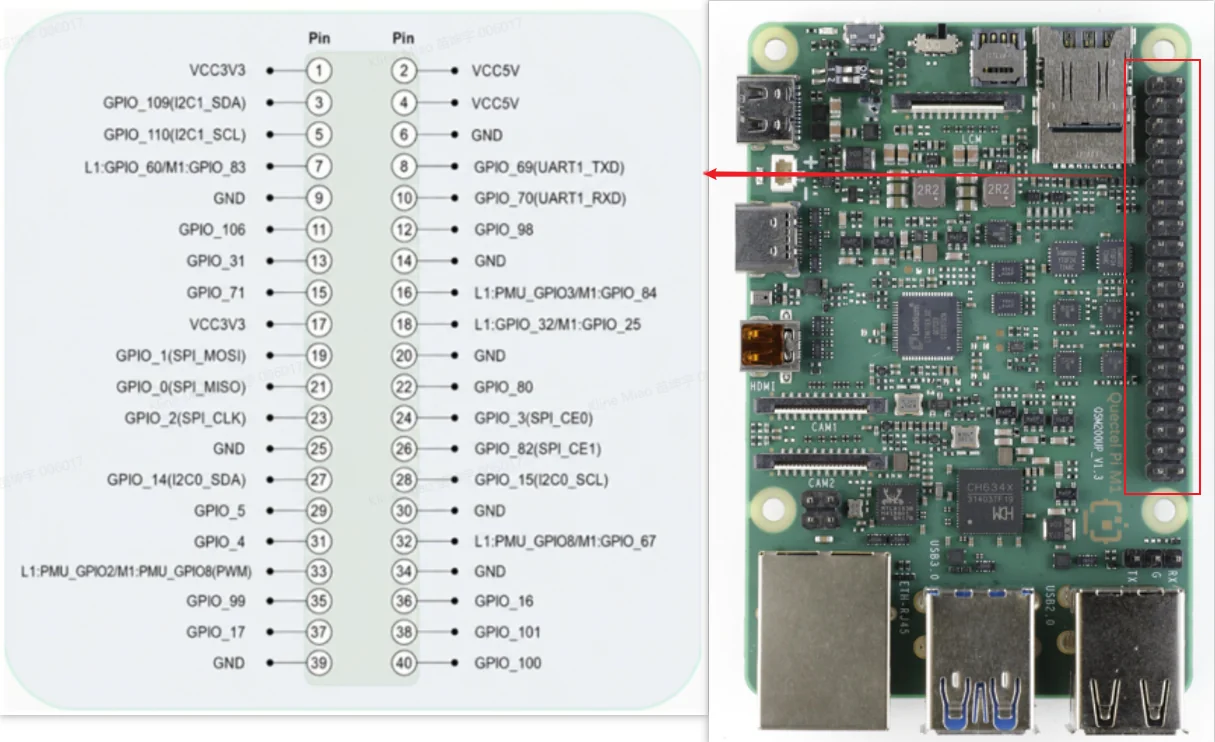
引脚定义
Function3 |
Function2 |
Function1 |
Default Function |
L1 GPIO# |
M1 GPIO# |
Pin# |
Pin# |
M1 GPIO# |
L1 GPIO# |
Default Function |
Function1 |
Function2 |
Function3 |
|---|---|---|---|---|---|---|---|---|---|---|---|---|---|
VCC 3V3 |
1 |
2 |
VCC 5V |
||||||||||
Common IIC SDA |
I2C SDA |
GPIO_109(I2C1_SDA) |
3 |
4 |
VCC 5V |
||||||||
Common IIC SCL |
I2C SCL |
GPIO_110(I2C1_SCL) |
5 |
6 |
GND |
||||||||
GPIO |
GPIO_60 |
GPIO_83 |
7 |
8 |
GPIO_69(UART1_TXD) |
UART TX |
SPI1_SCLK |
UART1_TX |
|||||
GND |
9 |
10 |
GPIO_70(UART1_RXD) |
UART RX |
SPI1_CS_N |
UART1_RX |
|||||||
GPIO |
GPIO_106 |
11 |
12 |
GPIO_98 |
GPIO |
||||||||
GPIO |
GPIO_31 |
13 |
14 |
GND |
|||||||||
UART2_TX |
SPI2_SCLK |
GPIO |
GPIO_71 |
15 |
16 |
GPIO_84 |
PMU_GPIO3 |
GPIO |
|||||
VCC 3V3 |
17 |
18 |
GPIO_25 |
GPIO_32 |
GPIO |
||||||||
I2C0_SCL |
UART0_RTS |
SPI0_MOSI |
SPI MOSI |
GPIO_1(SPI_MOSI) |
19 |
20 |
GND |
||||||
I2C0_SDA |
UART0_CTS |
SPI0_MISO |
SPI MISO |
GPIO_0(SPI_MISO) |
21 |
22 |
GPIO_80 |
GPIO |
SPI2_CS_N |
UART2_RX |
|||
UART0_TX |
SPI0_SCLK |
SPI CLK |
GPIO_2(SPI_CLK) |
23 |
24 |
GPIO_3(SPI_CE0) |
SPI CE0 |
SPI0_CS_N_0 |
UART0_RX |
||||
GND |
25 |
26 |
GPIO_82(SPI_CE1) |
SPI CE1 |
SPI0_CS_N_1 |
||||||||
I2C5_SDA |
UART5_CTS |
SPI5_MISO |
I2C SDA |
GPIO_14(I2C0_SDA) |
27 |
28 |
GPIO_15(I2C0_SCL) |
I2C SCL |
SPI5_MOSI |
UART5_RTS |
I2C5_SCL |
||
I2C1_SCL |
UART1_RTS |
SPI1_MOSI |
GPIO |
GPIO_5 |
29 |
30 |
GND |
||||||
I2C1_SDA |
UART1_CTS |
SPI1_MISO |
GPIO |
GPIO_4 |
31 |
32 |
GPIO_67 |
PMU_GPIO8 |
GPIO |
||||
PWM |
PWM |
PMU_GPIO2(PWM) |
PMU_GPIO8(PWM) |
33 |
34 |
GND |
|||||||
GPIO |
GPIO_99 |
35 |
36 |
GPIO_16 |
GPIO |
SPI5_SCLK |
UART5_TX |
||||||
UART5_RX |
SPI5_CS_N |
GPIO |
GPIO_17 |
37 |
38 |
GPIO_101 |
GPIO |
||||||
GND |
39 |
40 |
GPIO_100 |
GPIO |
|||||||||
GPIO测试
硬件连接
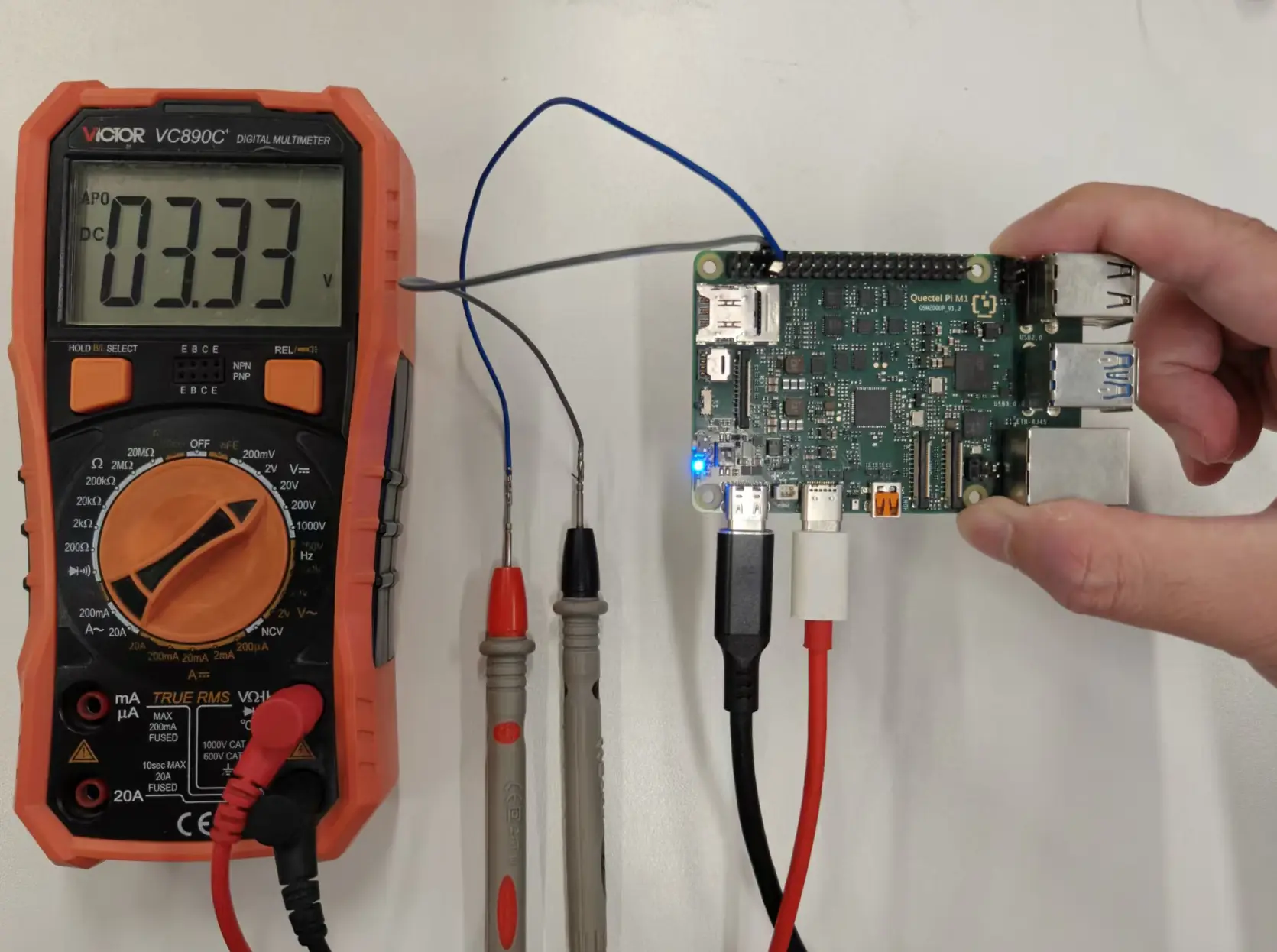
以 Pin13(GPIO_31)为例,万用表正极接 Pin13,负极接 GND(如 Pin14)。测试其他 GPIO 时,将命令里的 line offset 改成对应 GPIO 编号即可。
测试方法
进入 adb shell 后,使用 gpiod 命令测试 GPIO。普通 SoC GPIO 使用 gpiochip0,GPIO_31 对应 gpiochip0 line 31。
adb shell

# 查看 GPIO 控制器
gpiodetect

# 查看指定 GPIO 状态
gpioinfo gpiochip0 | grep -E "line[[:space:]]+31:"

# 读取 GPIO 当前电平
gpioget gpiochip0 31

# 拉高 GPIO,保持 10 秒
gpioset --mode=time --sec=10 gpiochip0 31=1

# 拉低 GPIO,保持 10 秒
gpioset --mode=time --sec=10 gpiochip0 31=0
GPIO 中断测试方法: 将待测 GPIO 接按键或外部信号源,让引脚电平发生变化;使用 gpiomon 监听该 GPIO 的上升沿和下降沿事件。这里仍以 GPIO_31 为例。
# 查看 GPIO_31 当前电平
gpioget gpiochip0 31

# 监听 GPIO_31 的上升沿、下降沿事件,触发 5 次后退出
gpiomon --num-events=5 --rising-edge --falling-edge gpiochip0 31
注意:如果报错 gpiodetect: error while loading shared libraries: libgpiod.so.2: cannot open shared object file: No such file or directory,先执行 export LD_LIBRARY_PATH=/opt/qcom/lib:$LD_LIBRARY_PATH 后再运行 gpiod 命令。
GPIO 边沿触发测试: 以 Pin13(GPIO_31) 为例,通过手动改变 GPIO 输入电平,使用 gpiomon 监听 GPIO 的上升沿和下降沿事件。
硬件连接
准备 3 根杜邦线,按照以下方式连接:
杜邦线 |
连接位置 |
用途 |
|---|---|---|
杜邦线 1 |
Pin1(3.3V) |
提供高电平 |
杜邦线 2 |
Pin39(GND) |
提供低电平 |
杜邦线 3 |
Pin13(GPIO_31) |
GPIO 输入测试端 |
三根杜邦线的另一端保持分开,不要将 3.3V 与 GND 直接连接。
执行:
gpiomon --rising-edge --falling-edge gpiochip0 31
命令进入监听状态后,按照以下方式操作:
将 Pin13 对应的杜邦线与 GND 杜邦线接触,使 GPIO_31 处于低电平。
将 Pin13 杜邦线与 GND 断开,再与 3.3V 杜邦线接触,使输入电平由低变高,此时产生上升沿。
将 Pin13 杜邦线 与 3.3V 断开,再与 GND 杜邦线接触,使输入电平由高变低,此时产生下降沿。
重复以上操作,终端输出类似:
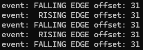
其中:
RISING EDGE: GPIO 输入电平由低变高。FALLING EDGE:GPIO 输入电平由高变低。
能够检测到对应的上升沿和下降沿事件,即表示 GPIO 边沿事件检测正常。
Note: 使用杜邦线手动切换 GPIO 输入电平时,连接或断开的瞬间可能因接触抖动产生多个连续边沿事件,该现象不影响 GPIO 边沿事件检测功能的判断。
万用表测量结果: 执行高电平输出时测得接近 3.3V,执行低电平输出时测得接近 0V,即可判定 GPIO 输出功能正常。
I2C测试
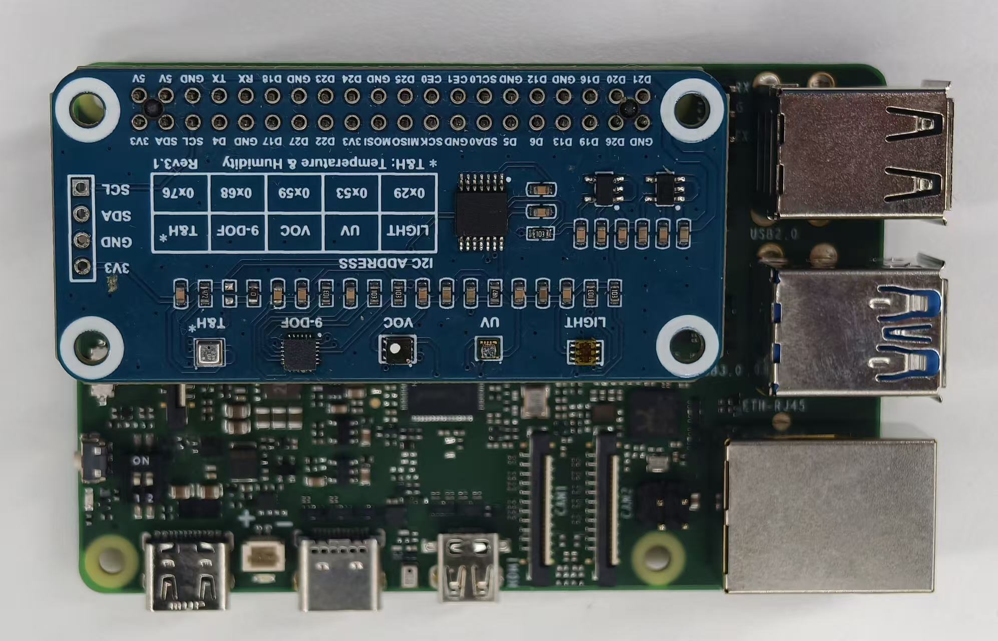
40‑pin接口的pin3和pin5默认为I2C的数据和时钟引脚。为了测试I2C接口,我们需要外接一个I2C设备。此处我们选用 微雪环境传感器扩展板,对应的设备节点为 /dev/i2c-1。
测试准备
|
|
|
|
|---|---|---|---|
TSL25911FN |
0x29 |
0x12 |
0x50 |
BME280 |
0x76 |
0xD0 |
0x60 |
MPU9250 |
0x68 |
0x75 |
0x71 |
LTR390-UV-1 |
0x53 |
0x06 |
0xB2 |
注:此处的TSL25911FN在读ID寄存器的时候需要带上command bit,也就是0xA0,即寄存器 0x12 实际访问时常写成 0xA0 | 0x12 = 0xB2,其他的不用。
本次测试使用微雪环境传感器扩展板,通过40‑pin接口进行连接。
硬件连接示意图:
测试方法
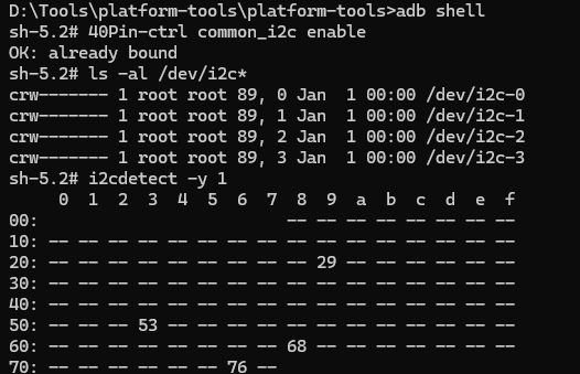
adb shell #进入ADB shell
ls -al /dev/i2c* #查看I2C-1是否在对应目录下
i2cdetect -y 1   #查看对应的I2C一共挂了多少个设备
I2C读取/写入
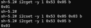
i2cget -y 1 0x53 0x05 b #读取i2c1下设备地址为0x53的0x05寄存器的值,大小为一个byte
i2cset -y 1 0x53 0x05 0x03 b #设置i2c1下设备地址为0x53的0x05寄存器的值,大小为一个byte
SPI测试
这里我们采用 2.23寸OLED扩展板
40-pin接口中的SPI功能对应的设备片选节点为 /dev/spidev0.0 和 /dev/spidev0.1。在adb中输入以下内容可查看这些节点:
adb shell #进入ADB shell
ls /dev/spidev* #查看SPI dev
微雪OLED显示器测试(CS0和CS1)
请按照以下表格进行接线:
OLED引脚 |
应该连接到 |
SC200U物理引脚 |
备注 |
|---|---|---|---|
VCC |
3.3V电源 |
Pin1或Pin17 |
必须是3.3V |
GND |
地线 |
Pin6/9/14等任意GND |
共地 |
DIN/MOSI |
SPI数据 |
Pin19 |
SPI_MOSI |
CLK/SCK |
SPI时钟 |
Pin23 |
SPI_CLK |
CS/CE |
片选 |
Pin24/Pin26 |
SPI_CE0/SPI_CE1 |
D/C |
数据/命令 |
Pin22 |
GPIO80 |
RES/RST |
复位 |
Pin18 |
M1: GPIO25 |
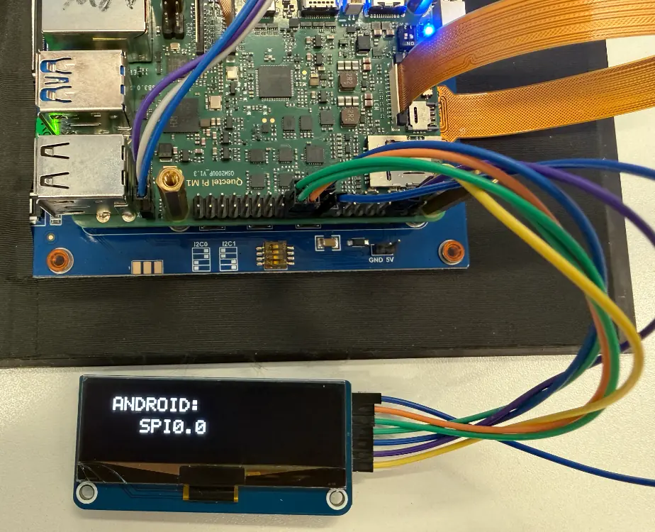
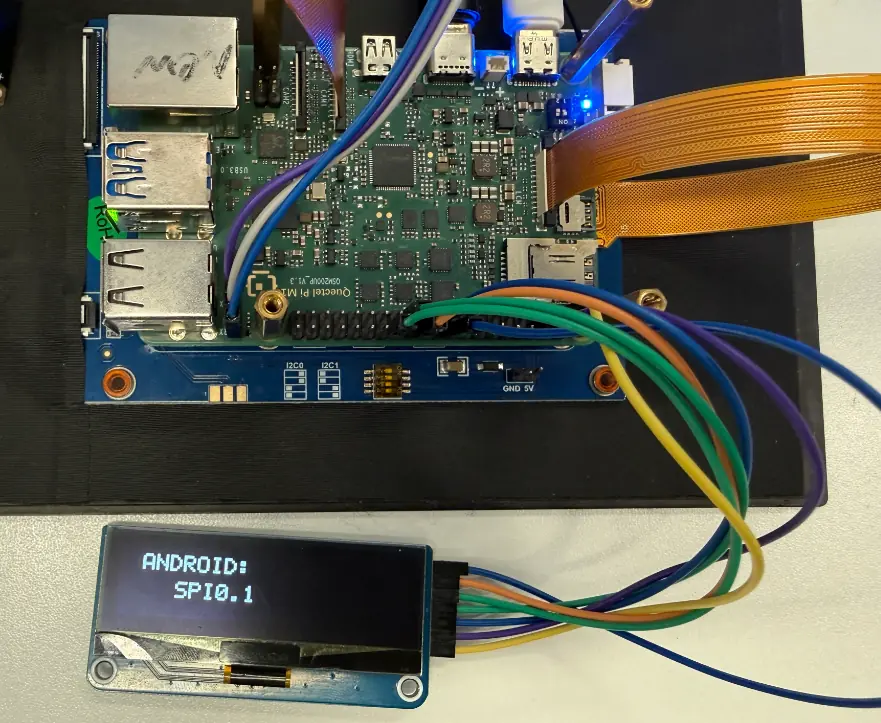
硬件连接示意图:
Linux宿主机创建SPI测试文件spi_oled_demo.c:
 #include <stdio.h>
 #include <stdlib.h>
 #include <stdint.h>
 #include <string.h>
 #include <unistd.h>
 #include <fcntl.h>
 #include <sys/ioctl.h>
 #include <linux/spi/spidev.h>
 #include <time.h>

#define GPIO_BASE   385
#define GPIO_RST    (GPIO_BASE + 32)
#define GPIO_DC     (GPIO_BASE + 80)
// 大多数 SSD1306/SH1106 SPI OLED 使用 MODE0,先改为 MODE0,降速到 4MHz 提高可靠性
#define SPI_MODE    SPI_MODE_0
#define SPI_SPEED   4000000

 #define OLED_WIDTH  128
 #define OLED_HEIGHT 32
 #define OLED_PAGES  4

 // Complete 5x7 font
 static const uint8_t font_5x7[][5] = {
     {0x00, 0x00, 0x00, 0x00, 0x00}, // Space
     {0x3E, 0x51, 0x49, 0x45, 0x3E}, // 0
     {0x00, 0x42, 0x7F, 0x40, 0x00}, // 1
     {0x42, 0x61, 0x51, 0x49, 0x46}, // 2
     {0x21, 0x41, 0x45, 0x4B, 0x31}, // 3
     {0x18, 0x14, 0x12, 0x7F, 0x10}, // 4
     {0x27, 0x45, 0x45, 0x45, 0x39}, // 5
     {0x3C, 0x4A, 0x49, 0x49, 0x30}, // 6
     {0x01, 0x71, 0x09, 0x05, 0x03}, // 7
     {0x36, 0x49, 0x49, 0x49, 0x36}, // 8
     {0x06, 0x49, 0x49, 0x29, 0x1E}, // 9
     {0x7E, 0x11, 0x11, 0x11, 0x7E}, // A
     {0x7F, 0x49, 0x49, 0x49, 0x36}, {0x3E, 0x41, 0x41, 0x41, 0x22}, // B C
     {0x7F, 0x41, 0x41, 0x22, 0x1C}, {0x7F, 0x49, 0x49, 0x49, 0x41}, // D E
     {0x7F, 0x09, 0x09, 0x09, 0x01}, {0x3E, 0x41, 0x49, 0x49, 0x7A}, // F G
     {0x7F, 0x08, 0x08, 0x08, 0x7F}, {0x00, 0x41, 0x7F, 0x41, 0x00}, // H I
     {0x20, 0x40, 0x41, 0x3F, 0x01}, {0x7F, 0x08, 0x14, 0x22, 0x41}, // J K
     {0x7F, 0x40, 0x40, 0x40, 0x40}, {0x7F, 0x02, 0x0C, 0x02, 0x7F}, // L M
     {0x7F, 0x04, 0x08, 0x10, 0x7F}, {0x3E, 0x41, 0x41, 0x41, 0x3E}, // N O
     {0x7F, 0x09, 0x09, 0x09, 0x06}, {0x3E, 0x41, 0x51, 0x21, 0x5E}, // P Q
     {0x7F, 0x09, 0x19, 0x29, 0x46}, {0x46, 0x49, 0x49, 0x49, 0x31}, // R S
     {0x01, 0x01, 0x7F, 0x01, 0x01}, {0x3F, 0x40, 0x40, 0x40, 0x3F}, // T U
     {0x1F, 0x20, 0x40, 0x20, 0x1F}, {0x3F, 0x40, 0x38, 0x40, 0x3F}, // V W
     {0x63, 0x14, 0x08, 0x14, 0x63}, {0x07, 0x08, 0x70, 0x08, 0x07}, // X Y
     {0x61, 0x51, 0x49, 0x45, 0x43}, // Z
     {0x08, 0x08, 0x08, 0x08, 0x08}, // -
     {0x00, 0x36, 0x36, 0x00, 0x00}, // :
     {0x00, 0x60, 0x60, 0x00, 0x00}, // .
 };

 static int char_to_index(char c) {
     if (c == ' ') return 0;
     if (c >= '0' && c <= '9') return 1 + (c - '0');
     if (c >= 'A' && c <= 'Z') return 11 + (c - 'A');
     if (c >= 'a' && c <= 'z') return 11 + (c - 'a');
     if (c == '-') return 37;
     if (c == ':') return 38;
     if (c == '.') return 39;
     return 0;
 }

 int gpio_write(int gpio, int value);
 void oled_quick_test(const char *device, const char *name);

  int main() {
     printf("\n╔════════════════════════════════════════════════════════╗\n");
     printf("║  Chip Select Pin Comparison Tool                      ║\n");
     printf("╚════════════════════════════════════════════════════════╝\n");

     printf("\nThis tool helps identify which CS pin is connected.\n");
     printf("\nInstruction:\n");
     printf("  1. Connect OLED CS to Pin24 first\n");
     printf("  2. Run test - should see display\n");
     printf("  3. Move OLED CS to Pin26\n");
     printf("  4. Run test again - should see display\n");
     printf("\n");
     char choice;
     printf("Which pin is your OLED CS currently connected to?\n");
     printf("  [0] Pin24 (CE0)\n");
     printf("  [1] Pin26 (CE1)\n");
     printf("Choice: ");
     scanf(" %c", &choice);

     if (choice == '0') {
         printf("\nTesting CE0 (Pin24)...\n");
         oled_quick_test("/dev/spidev0.0", "CE0-PIN24");
     } else if (choice == '1') {
         printf("\nTesting CE1 (Pin26)...\n");
         oled_quick_test("/dev/spidev0.1", "CE1-PIN26");
     } else {
         printf("Invalid choice\n");
         return 1;
     }

     return 0;
 }

 void oled_quick_test(const char *device, const char *name) {
     // Display buffer
     static uint8_t buffer[OLED_PAGES][OLED_WIDTH];

     // Simple GPIO functions
     int gpio_export(int gpio) {
         int fd = open("/sys/class/gpio/export", O_WRONLY);
         if (fd < 0) return -1;
         char buf[10];
         snprintf(buf, sizeof(buf), "%d", gpio);
         write(fd, buf, strlen(buf));
         close(fd);
         usleep(100000);
         return 0;
     }

      int gpio_set_dir(int gpio) {
         char path[50];
         snprintf(path, sizeof(path), "/sys/class/gpio/gpio%d/direction", gpio);
         int fd = open(path, O_WRONLY);
         if (fd < 0) return -1;
         write(fd, "out", 3);
         close(fd);
         return 0;
     }

     int gpio_write(int gpio, int value) {
         char path[50];
         snprintf(path, sizeof(path), "/sys/class/gpio/gpio%d/value", gpio);
         int fd = open(path, O_WRONLY);
         if (fd < 0) return -1;
         char buf[2] = {value ? '1' : '0', 0};
         write(fd, buf, 1);
         close(fd);
         return 0;
     }

     int configure_spi(int fd) {
         uint8_t mode = SPI_MODE;
         uint32_t speed = SPI_SPEED;

         if (ioctl(fd, SPI_IOC_WR_MODE, &mode) < 0) {
             perror("  ERROR: Cannot set SPI mode");
             return -1;
         }
         if (ioctl(fd, SPI_IOC_WR_MAX_SPEED_HZ, &speed) < 0) {
             perror("  ERROR: Cannot set SPI speed");
             return -1;
         }

         printf("  SPI configured: mode %u, speed %u Hz\n", mode, speed);
         return 0;
     }

     void send_cmd(int fd, uint8_t cmd) {
         gpio_write(GPIO_DC, 0);
         write(fd, &cmd, 1);
         usleep(1000);
     }

      void set_pixel(int x, int y, int color) {
         if (x >= 0 && x < OLED_WIDTH && y >= 0 && y < OLED_HEIGHT) {
             int page = y / 8;
             int bit = y % 8;
             if (color)
                 buffer[page][x] |= (1 << bit);
             else
                 buffer[page][x] &= ~(1 << bit);
         }
     }

     void draw_char(int x, int y, char c) {
         int idx = char_to_index(c);
         for (int col = 0; col < 5; col++) {
             uint8_t data = font_5x7[idx][col];
             for (int row = 0; row < 8; row++) {
                 if (data & (1 << row)) {
                     set_pixel(x + col, y + row, 1);
                 }
             }
         }
     }

     void draw_text(int x, int y, const char *text) {
         int cursor = x;
         while (*text) {
             draw_char(cursor, y, *text);
             cursor += 6;
             text++;
         }
     }

     void clear_buffer() {
         memset(buffer, 0, OLED_PAGES * OLED_WIDTH);
     }

     void display_buffer(int fd) {
         for (int page = 0; page < OLED_PAGES; page++) {
             send_cmd(fd, 0xB0 + page);
             send_cmd(fd, 0x04);
             send_cmd(fd, 0x10);
             gpio_write(GPIO_DC, 1);
             write(fd, buffer[page], OLED_WIDTH);
         }
     }

     // Initialize GPIO
     gpio_export(GPIO_RST);
     gpio_export(GPIO_DC);
     usleep(200000);
     gpio_set_dir(GPIO_RST);
     gpio_set_dir(GPIO_DC);

     // Open SPI
     printf("  Opening %s...\n", device);
     int spi_fd = open(device, O_RDWR);
     if (spi_fd < 0) {
         perror("  ERROR: Cannot open device");
         printf("  → %s is NOT working or OLED not connected\n", name);
         return;
     }
     printf("  ✓ Device opened\n");

     // Configure SPI
     if (configure_spi(spi_fd) < 0) {
         printf("  → %s SPI configuration failed\n", name);
         close(spi_fd);
         return;
     }

     // Reset OLED
     printf("  Resetting OLED...\n");
     gpio_write(GPIO_RST, 0);
     usleep(50000);
     gpio_write(GPIO_RST, 1);
     usleep(50000);

     // Initialize OLED
     printf("  Initializing OLED...\n");
     send_cmd(spi_fd, 0xAE);
     send_cmd(spi_fd, 0x04); send_cmd(spi_fd, 0x10); send_cmd(spi_fd, 0x40);
     send_cmd(spi_fd, 0x81); send_cmd(spi_fd, 0xFF);
     send_cmd(spi_fd, 0xA1); send_cmd(spi_fd, 0xA6);
     send_cmd(spi_fd, 0xA8); send_cmd(spi_fd, 0x1F);
     send_cmd(spi_fd, 0xC8);
     send_cmd(spi_fd, 0xD3); send_cmd(spi_fd, 0x00);
     send_cmd(spi_fd, 0xD5); send_cmd(spi_fd, 0xF0);
     send_cmd(spi_fd, 0xD8); send_cmd(spi_fd, 0x05);
     send_cmd(spi_fd, 0xD9); send_cmd(spi_fd, 0xC2);
     send_cmd(spi_fd, 0xDA); send_cmd(spi_fd, 0x12);
     send_cmd(spi_fd, 0xDB); send_cmd(spi_fd, 0x08);
     send_cmd(spi_fd, 0xAF);
     printf("  ✓ OLED initialized\n");

     // Test 1: Display "USING: CE0" or "USING: CE1"
     printf("\n  [Test 1] Displaying chip select info...\n");
     clear_buffer();
     draw_text(10, 4, "USING:");
     if (strstr(name, "CE0")) {
         draw_text(25, 16, "CE0");
     } else {
         draw_text(25, 16, "CE1");
     }
     display_buffer(spi_fd);
     printf("  ✓ Screen showing: USING %s\n", strstr(name, "CE0") ? "CE0" : "CE1");
     sleep(3);

     // Test 2: Fill white
     printf("\n  [Test 2] Filling screen WHITE...\n");
     memset(buffer, 0xFF, OLED_PAGES * OLED_WIDTH);
     display_buffer(spi_fd);
     printf("  ✓ Screen should be WHITE\n");
     sleep(2);

     // Test 3: Blink test
     printf("\n  [Test 3] Blink test (5 times)...\n");
     for (int i = 0; i < 5; i++) {
         // White
         memset(buffer, 0xFF, OLED_PAGES * OLED_WIDTH);
         display_buffer(spi_fd);
         usleep(200000);

         // Black
         memset(buffer, 0x00, OLED_PAGES * OLED_WIDTH);
         display_buffer(spi_fd);
         usleep(200000);

         printf("    Blink %d/5\n", i + 1);
     }
     printf("  ✓ Blink test complete\n");

     // Test 4: FPS Performance Test
     printf("\n  [Test 4] FPS Performance Test...\n");
     printf("  Running 100 frame updates...\n");

     struct timespec start, end;
     clock_gettime(CLOCK_MONOTONIC, &start);

     for (int frame = 0; frame < 100; frame++) {
         // Generate test pattern
         for (int page = 0; page < OLED_PAGES; page++) {
             for (int x = 0; x < OLED_WIDTH; x++) {
                 buffer[page][x] = (x + frame) & 0xFF;
             }
         }
         display_buffer(spi_fd);
     }

     clock_gettime(CLOCK_MONOTONIC, &end);
     double elapsed = (end.tv_sec - start.tv_sec) +
                      (end.tv_nsec - start.tv_nsec) / 1000000000.0;
     double fps = 100.0 / elapsed;

     printf("  ✓ Performance: %.1f FPS\n", fps);

     // Display FPS result on screen
     clear_buffer();
     draw_text(10, 4, "FPS TEST");
     char fps_str[20];
     snprintf(fps_str, sizeof(fps_str), "%.1f FPS", fps);
     draw_text(20, 16, fps_str);
     display_buffer(spi_fd);
     printf("  ✓ FPS result displayed on screen\n");
     sleep(3);

     // Test 5: CS Pin Functionality Test
     printf("\n  [Test 5] CS Pin Functionality Test...\n");
     printf("  This test verifies CS pin actually controls the device\n");

     // Step 1: Display number 1
     printf("  Step 1: Displaying pattern 1...\n");
     clear_buffer();
     draw_text(15, 4, "PATTERN");
     draw_text(50, 16, "1");
     display_buffer(spi_fd);
     sleep(2);

     // Step 2: Try to update through the OTHER CS (should fail if CS works)
     printf("  Step 2: Trying to update via OTHER CS...\n");
     const char *other_device = strstr(name, "CE0") ? "/dev/spidev0.1" : "/dev/spidev0.0";
     const char *other_name = strstr(name, "CE0") ? "CE1" : "CE0";

     int other_fd = open(other_device, O_RDWR);
     if (other_fd >= 0) {
         if (configure_spi(other_fd) < 0) {
             close(other_fd);
             printf("  Skipping %s update because SPI configuration failed\n", other_name);
             goto update_back;
         }

         // Try to display pattern 2 via other CS
         clear_buffer();
         draw_text(15, 4, "PATTERN");
         draw_text(50, 16, "2");

         for (int page = 0; page < OLED_PAGES; page++) {
             send_cmd(other_fd, 0xB0 + page);
             send_cmd(other_fd, 0x04);
             send_cmd(other_fd, 0x10);
             gpio_write(GPIO_DC, 1);
             write(other_fd, buffer[page], OLED_WIDTH);
         }

         close(other_fd);
         printf("  Sent update via %s (other CS)\n", other_name);
         sleep(2);

         printf("\n  ╔════════════════════════════════════════════════╗\n");
         printf("  ║ CHECK SCREEN: Still showing '1' or changed to '2'? ║\n");
         printf("  ╚════════════════════════════════════════════════╝\n");
         printf("\n  If still showing '1': CS pin is WORKING correctly ✓\n");
         printf("  If changed to '2': CS pin NOT working (both CS active) ✗\n\n");
         sleep(2);
     }

     // Step 3: Update back via correct CS
update_back:
     printf("  Step 3: Updating via correct CS (%s)...\n", name);
     clear_buffer();
     draw_text(15, 4, "BACK TO");
     draw_text(50, 16, "1");
     display_buffer(spi_fd);
     printf("  ✓ Should see pattern 1 again\n");
     sleep(2);

     // Test 6: FPS result summary
     printf("\n  [Test 6] Final Summary...\n");
     clear_buffer();
     draw_text(30, 4, name);
     char summary_str[20];
     snprintf(summary_str, sizeof(summary_str), "%.1fFPS", fps);
     draw_text(20, 16, summary_str);
     display_buffer(spi_fd);
     printf("  ✓ Summary displayed\n");
     sleep(3);

     // Clear screen
     clear_buffer();
     display_buffer(spi_fd);

     close(spi_fd);

     printf("\n======================================================================\n");
     printf("  %s Test Complete!\n", name);
     printf("======================================================================\n");
     printf("  CS Pin Test Result:\n");
     printf("    If screen didn't change to '2' in Step 2:\n");
     printf("      → CS pin is working correctly ✓\n");
     printf("    If screen changed to '2':\n");
     printf("      → CS pin might not be controlling the device ✗\n");
     printf("      → Both CS pins may be active simultaneously\n");
     printf("\n  Performance: %.1f FPS\n", fps);
     printf("======================================================================\n");
 }
创建完成之后将其编译成可执行文件:
mkdir -p out #创建输出目录
aarch64-linux-gnu-gcc spi_oled_demo.c -O2 -Wall -Wextra -o spi_oled_demo #编译成可执行文件
将编译好的文件从Linux环境copy到adb shell同级目录下。
执行步骤:
adb push spi_oled_demo /tmp/spi_oled_demo
adb shell chmod +x /tmp/spi_oled_demo
adb shell
/tmp/spi_oled_demo
程序运行后会提示选择SPI设备:
选择0:使用
/dev/spidev0.0(CE0, Pin24)选择1:使用
/dev/spidev0.1(CE1, Pin26)
请根据实际接线情况选择对应的设备(CS/CE引脚连接到pin24则选择0,连接到pin26则选择1)。
测试结果:
程序执行后会依次进行以下测试:
╔══════════════════════════════════════════════════════╗
║        Android SPI OLED 测试程序                     ║
║        适配Android设备                               ║
╚══════════════════════════════════════════════════════╝

选择SPI设备:
  [0] /dev/spidev0.0 (CE0, Pin24)
  [1] /dev/spidev0.1 (CE1, Pin26)
  [c] 自定义设备路径
选择: 1

使用设备: /dev/spidev0.1

初始化GPIO...
  ✓ GPIO初始化成功

打开SPI设备: /dev/spidev0.1
  ✓ SPI设备已打开并配置
    - 模式: 3
    - 速度: 2000000 Hz
    - 位宽: 8 bits

初始化OLED...
  复位OLED...
  发送初始化命令...
  ✓ OLED初始化完成

━━━━━━━━━━━━━━━━━━━━━━━━━━━━━━━━━━━━━━━━━━━━━━
  开始测试序列: SPI0.1
━━━━━━━━━━━━━━━━━━━━━━━━━━━━━━━━━━━━━━━━━━━━━━

[测试1] 显示设备信息...
  ✓ 屏幕应显示: ANDROID SPI0.1

[测试2] 全白屏测试...
  ✓ 屏幕应全白

[测试3] 闪烁测试 (5次)...
    闪烁 1/5
    闪烁 2/5
    闪烁 3/5
    闪烁 4/5
    闪烁 5/5
  ✓ 闪烁测试完成

[测试4] FPS性能测试...
  运行100帧更新...
  ✓ 性能: 40.3 FPS (耗时: 2.48秒)
  ✓ FPS结果已显示

[测试5] 图案测试...
  图案1: 横条纹
  图案2: 竖条纹
  图案3: 棋盘格
  ✓ 图案测试完成

[测试6] 测试总结...
  ✓ 总结已显示
测试说明:
测试1:验证OLED能够正常显示文本信息
测试2:验证OLED全屏显示功能
测试3:通过闪烁测试验证OLED刷新功能
测试4:测试SPI通信性能(FPS值)
测试5:测试不同图案显示功能
测试6:显示测试总结信息
若所有测试项均显示 ✓ 标记,则表明SPI通信与OLED功能一切正常。
UART测试
在 40-pin 接口中,pin8 和 pin10 默认配置为 UART 功能,对应的设备节点为 /dev/ttyHS0。
查看串口设备
可以使用以下命令查看系统中所有的串口设备:
ls /dev/tty*
UART回环测试
本测试通过将 pin8 和 pin10 短接,验证串口收发功能是否正常。
硬件连接: 将40‑pin的pin8(TX)和pin10(RX)短接。
Linux宿主机创建UART测试文件:
新建 uart_loopback.c 文件,内容如下:
#include <stdio.h>
#include <stdlib.h>
#include <string.h>
#include <unistd.h>
#include <fcntl.h>
#include <termios.h>
#include <errno.h>
#include <signal.h>

static int serial_fd = -1;
static volatile int running = 1;

void signal_handler(int sig) {
    printf("\n用户中断测试\n");
    running = 0;
    if (serial_fd >= 0) {
        close(serial_fd);
        printf("串口已关闭\n");
    }
    exit(0);
}

int configure_serial(int fd, int baudrate) {
    struct termios tty;

    if (tcgetattr(fd, &tty) != 0) {
        printf("获取串口属性失败: %s\n", strerror(errno));
        return -1;
    }

    speed_t speed;
    switch (baudrate) {
        case 9600:   speed = B9600;   break;
        case 19200:  speed = B19200;  break;
        case 38400:  speed = B38400;  break;
        case 57600:  speed = B57600;  break;
        case 115200: speed = B115200; break;
        case 230400: speed = B230400; break;
        default:     speed = B115200; break;
    }

    cfsetospeed(&tty, speed);
    cfsetispeed(&tty, speed);

    tty.c_cflag &= ~PARENB;
    tty.c_cflag &= ~CSTOPB;
    tty.c_cflag &= ~CSIZE;
    tty.c_cflag |= CS8;
    tty.c_cflag &= ~CRTSCTS;
    tty.c_cflag |= CREAD | CLOCAL;

    tty.c_iflag &= ~(IXON | IXOFF | IXANY);
    tty.c_iflag &= ~(ICANON | ECHO | ECHOE | ISIG);

    tty.c_oflag &= ~OPOST;

    tty.c_lflag &= ~(ICANON | ECHO | ECHOE | ISIG);

    tty.c_cc[VTIME] = 10;
    tty.c_cc[VMIN] = 0;

    if (tcsetattr(fd, TCSANOW, &tty) != 0) {
        printf("设置串口属性失败: %s\n", strerror(errno));
        return -1;
    }

    return 0;
}

int serial_loopback_test(const char* port, int baudrate) {
    char test_data[] = "Hello, Serial Loopback!";
    char received_data[256];
    ssize_t bytes_written, bytes_read;

    serial_fd = open(port, O_RDWR | O_NOCTTY | O_SYNC);
    if (serial_fd < 0) {
        printf("无法打开串口 %s: %s\n", port, strerror(errno));
        return -1;
    }

    if (configure_serial(serial_fd, baudrate) != 0) {
        close(serial_fd);
        return -1;
    }

    printf("串口 %s 已打开,开始回环测试(按Ctrl+C退出)...\n", port);

    while (running) {
        tcflush(serial_fd, TCIOFLUSH);

        bytes_written = write(serial_fd, test_data, strlen(test_data));
        if (bytes_written < 0) {
            printf("发送数据失败: %s\n", strerror(errno));
            break;
        }
        printf("发送: %s\n", test_data);

        usleep(100000);

        bytes_read = read(serial_fd, received_data, sizeof(received_data) - 1);
        if (bytes_read < 0) {
            printf("读取数据失败: %s\n", strerror(errno));
            break;
        }

        received_data[bytes_read] = '\0';

        if (bytes_read == (ssize_t)strlen(test_data) &&
            strncmp(received_data, test_data, strlen(test_data)) == 0) {
            printf("接收: %s → 测试通过\n\n", received_data);
        } else {
            printf("接收异常: 发送[%zu] vs 接收[%zd] → 测试失败\n",
                   strlen(test_data), bytes_read);
            if (bytes_read > 0) {
                printf("接收内容: %s\n\n", received_data);
            } else {
                printf("未接收到数据\n\n");
            }
        }

        sleep(1);
    }

    close(serial_fd);
    printf("串口 %s 已关闭\n", port);
    return 0;
}

void print_usage(const char* prog) {
    printf("UART回环测试程序\n\n");
    printf("用法:\n");
    printf("  %s -n <HS编号> [-b 波特率]     指定ttyHS编号\n", prog);
    printf("  %s -d <设备路径> [-b 波特率]    指定完整设备路径\n", prog);
    printf("  %s                             默认使用 /dev/ttyHS5 @ 115200\n\n", prog);
    printf("示例:\n");
    printf("  %s -n 3                  使用 /dev/ttyHS3 @ 115200\n", prog);
    printf("  %s -n 5 -b 9600         使用 /dev/ttyHS5 @ 9600\n", prog);
    printf("  %s -d /dev/ttyUSB0      使用 /dev/ttyUSB0 @ 115200\n", prog);
}

int main(int argc, char* argv[]) {
    char port_buf[64];
    const char* port = "/dev/ttyHS5";
    int baudrate = 115200;
    int opt;

    while ((opt = getopt(argc, argv, "n:d:b:h")) != -1) {
        switch (opt) {
            case 'n':
                snprintf(port_buf, sizeof(port_buf), "/dev/ttyHS%s", optarg);
                port = port_buf;
                break;
            case 'd':
                port = optarg;
                break;
            case 'b':
                baudrate = atoi(optarg);
                break;
            case 'h':
            default:
                print_usage(argv[0]);
                return (opt == 'h') ? 0 : 1;
        }
    }

    signal(SIGINT, signal_handler);
    signal(SIGTERM, signal_handler);

    printf("UART回环测试程序\n");
    printf("使用串口: %s\n", port);
    printf("波特率: %d\n", baudrate);
    printf("=====================================\n");

    return serial_loopback_test(port, baudrate);
}
创建完成之后将其编译成可执行文件:
mkdir -p out #创建输出目录
aarch64-linux-gnu-gcc uart_loopback.c -O2 -Wall -Wextra -o out/uart_loopback #编译成可执行文件
将编译好的文件从Linux环境copy到adb shell同级目录下
执行步骤:
adb push uart_loopback /tmp/uart_loopback
adb shell chmod +x /tmp/uart_loopback
adb shell
/tmp/uart_loopback /dev/ttyHS1
测试结果:
当pin8和pin10正确短接时,程序会持续发送数据并验证接收的数据是否一致:
UART回环测试程序
使用串口: /dev/ttyHS1
波特率: 115200
=====================================
串口 /dev/ttyHS1 已打开,开始回环测试(按Ctrl+C退出)...
发送: Hello, Serial Loopback!
接收: Hello, Serial Loopback! → 测试通过

发送: Hello, Serial Loopback!
接收: Hello, Serial Loopback! → 测试通过

发送: Hello, Serial Loopback!
接收: Hello, Serial Loopback! → 测试通过
按 Ctrl+C 可退出测试程序。程序会自动关闭串口并退出。
温控风扇测试
后台进程检测/sys/class/thermal/thermal_zone*
并轮读几个核的温度取最高,并且根据最高温度来配置风扇的PWM占空比。
|
|
|---|---|
<30℃ |
0 |
30~40℃ |
64 |
40~50℃ |
128 |
50~60℃ |
192 |
>60℃ |
255 |
接线图
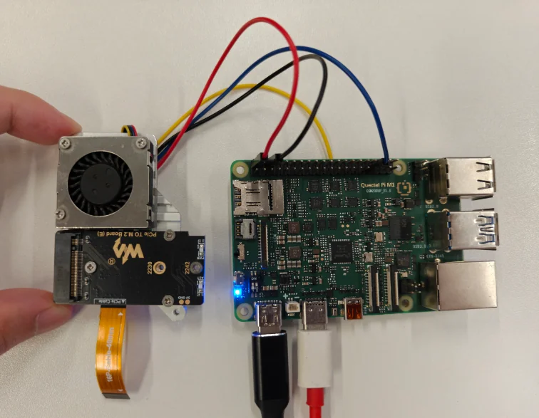
此次采用 树莓派风扇,根据图示接到对应的M1/L1 40Pin引脚上。
风扇引脚 |
M1开发板引脚(40PIN) |
|---|---|
红线(电源正极) |
PIN2 |
黑线(电源负极) |
PIN6 |
蓝线(PWM) |
PIN33 |
黄线(转速检测) |
不接 |
测试流程
默认风扇功能是关闭的,开机后输入对应指令查看风扇服务的状态。
adb shell
40pin-ctrl fan status #查看当前风扇服务的状态,未启用风扇服务为bound,启用为enable
40pin-ctrl fan enable #使能风扇服务,使能后可以查看下状态是否为enable
40pin-ctrl fan disable #关闭风扇服务,停止测试才需要输入该指令
在第一个终端里面输入。
40pin-ctrl fan enable
40pin-ctrl fan status
#M1
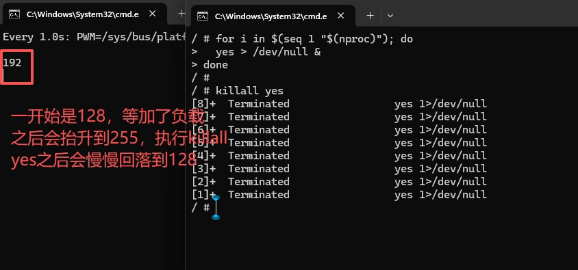
watch -n 1 'PWM=/sys/bus/platform/devices/1c40000.qcom,spmi:qcom,pm6125@1:qcom,pwms@b300/pwm/pwmchip0/pwm0; p=$(cat "$PWM/period"); d=$(cat "$PWM/duty_cycle"); echo $(( (d * 255 + p / 2) / p ))'
#L1
watch -n 1 'PWM=/sys/bus/platform/devices/1c40000.qcom,spmi:qcom,pm2250@1:qcom,pwms@be00/pwm/pwmchip2/pwm0; p=$(cat "$PWM/period"); d=$(cat "$PWM/duty_cycle"); echo $(( (d * 255 + p / 2) / p ))'
查看当前的温度和PWM占空比是不是对得上。
开第二个终端,做升温。
for i in 1 2 3 4; do
  yes > /dev/null &
done
如果第3步里面的升温不够可以把负载调大。
for i in $(seq 1 $(nproc)); do
  yes > /dev/null &
done
看两个终端里面的温度和风扇的PWM占空比是不是和表里面的对齐。
测试结束后停止负载。
killall yes